2

I cannot understand how this IC works from the block diagram given in the datasheet. I understand the concept of an H-bridge, but cannot figure how this one operates.

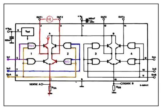
I drew on the schematic to illustrate my confusion.

To run a motor in the given way (red path) you would need to enable the transistor in the top left and bottom right, while disabling the other two. Do to that, the AND gates at the base of those transistors (conducting) need to have two HIGH terminals in order to provide feeder current for the transistors.

However, in order to turn on only those two transistors, you must enable IN1, IN2, and ENA (ENA is simply a pin you enable to power the left H-Bridge of the L298N - is has two as shown).

Given how the wires are connected, there is no way - that I can see apparently - to turn on two diagonal transistors without enabling the other two ..


I obviously must be missing something ..

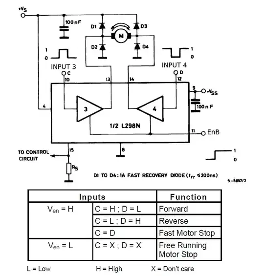
According to what I have read, in order to drive the transistors you need to have IN1 HIGH and IN2 LOW for one direction and the opposite for the other. I just do not see, from this schematic, how that even is possible.

Also note: the ENA/ENB pins are used in conjunction with PWN signals to drive the motor are variable speeds.


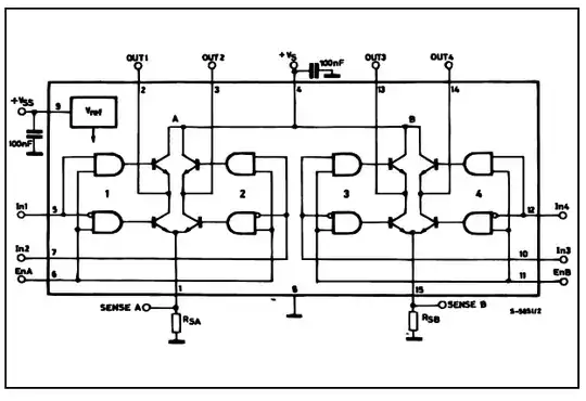
Here is the original:

enter image description here

Here is the illustration:

enter image description here

sherrellbc
  • 3,431
  • 6
  • 35
  • 62

2 Answers2

2

If you take the logic step by step, let's say:

ENA = 1, IN1 = 1, IN2 = 0

(left is the IN, right the EN input, ~ stands for inverted by the bubble)

So the top left AND gate:

1 + 1 = 1

bottom left AND gate:

~1 + 1 = 0

Top right AND gate:

0 + 1 = 0

Bottom right AND gate:

~0 + 1 = 1

So in this case the top left and bottom right transistor are turned on.

Oli Glaser
  • 54,990
  • 3
  • 76
  • 147
1

The two IN connections determine the direction of the motor.

enter image description here

The ENABLE is connected to the 4 AND gates so when ENABLE is HIGH all the gates will be enabled.

Note that ONE of the inputs to each side of the bridge is negated (o) so the top of each half bridge is turned ON with IN = HIGH but the bottom gate will be OFF and vice versa.

If the two IN signals are the same (both HIGH or both LOW) either the two top or the two bottom transistors are turned ON and this this acts as a brake.

If one IN is HIGH and the other LOW then opposite sides of the bridge will be turned ON and current will flow. The direction is determined by which IN has been set high.

JIm Dearden
  • 18,926
  • 30
  • 40
  • I did not even catch the inverting symbols at the AND gates - or more specifically I did not know what it meant. Thanks for the post! – sherrellbc Aug 11 '13 at 18:45