16

I'm in need of a diplexer that'll separate RF signals from a single feedline to two antennas. What I designed and built was a diplexer that would allow ~38 Mhz and below out port 1, with ~38 MHz and above out port 2. This is primarily to use a separate antenna on the 6M ham band and a separate antenna for the remaining HF frequencies with an output power of 100 watts.

I followed these directions: http://vk3atl.org/technical/Diplexer_1cc.pdf (PDF) using the student version of Elsie. Layed out a PCB, etched it, populated with the parts calculated by Elsie. Here's the design:
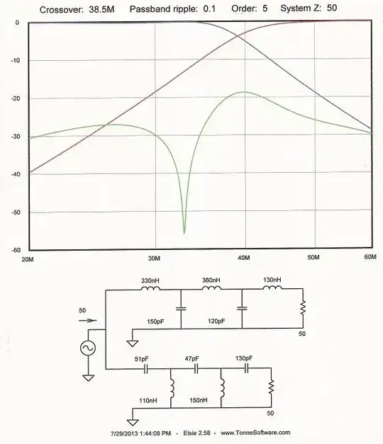
enter image description here

As built:

enter image description here

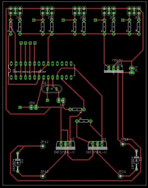
I soldered a 51 ohm resistor across each output port, then fed the input with an MFJ analyser. Below the crossover, SWR is ~1.7:1. Above the crossover, the SWR ~2.1:1. I was thinking the SWR should have been lower on both ports - around 1.5:1 or better. 1.7:1 isn't all that bad for the HF port but >2.0:1 on the VHF port isn't. My initial thoughts are the coils are too close together and need to be spread out. That's all I can think of at this point. I would redesign the PCB to have more distance between coils and make them orthogonal. What other modifications to this design should I do?

UPDATED

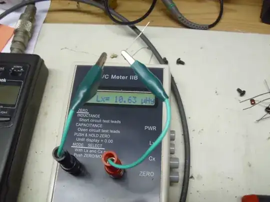
Pulled one of the 51 ohm resistors off the board and tested it with my LC meter. Sure enough, it looks like these resistors are wirewound.

Measuring inductance of a wirewound resistor

EDITED to reduce image sizes

MarkSchoonover
  • 1,113
  • 10
  • 17
  • 1
    Are you sure the output resistors are non-inductive? They may be causing impedance-mismatches on the output, and producing all sorts of fun spurious readings. Unless they're carbon-comp, they're going to act like little inductors. – Connor Wolf Aug 11 '13 at 06:39
  • At what frequencies did you measure SWR on both ports? Also, what is the green curve on the graph - return loss at input? – Andy aka Aug 11 '13 at 10:02
  • @Conner - Indeed, these resistors are wire wound. See updated photo. – MarkSchoonover Aug 11 '13 at 17:28
  • @Andy - I swept from 1.6MHz up through 60MHz. I believe the green line is return loss but I don't have access to the help file at the moment to confirm. – MarkSchoonover Aug 11 '13 at 17:29
  • 7
    They're not actually wire-wound. The way a lot of axial resistors are made is that the resistor is a ceramic cylinder, which is coated with resistive compound. Metal end-caps are then crimped onto the cylinder. The resistance is then tuned by cutting a **helical groove in the resistive compound** (with a laser or something similar). Finally, it's dipped in epoxy. This helical conductive path will have potentially significant inductance at high frequency. – Connor Wolf Sep 21 '13 at 21:34
  • Now that it exists (in beta), I would suggest moving this question to the [Amateur Radio Stack Exchange](http://ham.stackexchange.com/). – Scott Winder Nov 13 '13 at 16:59
  • How do I move?? – MarkSchoonover Jan 14 '14 at 20:07

1 Answers1

1

What your trying to do here is build two filters, one high pass, and one low pass. Horizontal inductors shunted to ground with caps, create a low pass filter. When the caps are horizontal and the inductors got to ground, you have a high pass filter.

If you want to analyize this in detail you need to learn how to use a technique called ABCD matricies.

http://en.wikipedia.org/wiki/ABCD_matrix_analysis

Each series or shunt impedance is entered into the 2x2 matrix, and then they are multiplied and you get a final relationship that describes the circuit.

For a simple circuit as you have here. there is no reason to go to the trouble, as it is already well understood. The circuits are equavilent to a transmission line, below a critical frequency, and a low or high pass filter above. There are simple formulae that give the cutoff freq and the characteristic impedance of the circuit.

These circuits need to be terminated in their characteristic impedance, or they will not work properly, and in that case you will get standing waves.

Your antenna has an impedance, so the filters need to be designed to work into that load impedance.

Jont Allen
  • 46
  • 2