22

Working with some circuits this summer, I ran into what everyone eventually does: Current flows from + to - despite the electrons flowing (well, bumping into eachother) from - to +. I understand the historical background for this, but for me that raises this question:

If I strung an arbitrarily large number of bidirectional incandescent light bulbs on a wire of a length of say 10 light seconds, and hooked it up to a sufficiently powerful battery, what would happen? Would the light bulbs all light up at once? Would they light up from + to -, from - to +? Thank you in advance. This has been really bugging me.

Tom
  • 223
  • 1
  • 4
  • How is the battery being connected? is it already connected to one of the battery terminals and you would just be connecting the other side or would both leads be connected to the batter at the same time? – Gorloth Aug 08 '13 at 04:17
  • I didn't think of that, nor do I know if it would make a difference. Let's say you do it three times, doing it first positive then negative, then negative positive, then both at the same time. – Tom Aug 08 '13 at 04:22
  • 4
    I would think when you have a circuit that is very long (10 light secconds) having one lead connected to the battery would put the circuit at that potential, so connecting the other lead would cause a pulse down the wire, transmission line stuff and all (I think that applies in this situation) – Gorloth Aug 08 '13 at 04:35
  • 3
    Where are you standing with respect to the lights? If you are 10 light seconds from the furthest light and it lights first, you may see all lights come on at once... – SLaG Aug 08 '13 at 04:43
  • @Gorloth, yes it will be a voltage wave starting from the last terminal connected. Transmission line theory applies here. – travisbartley Aug 08 '13 at 04:44
  • @ThePhoton but then why is it that when you connect a polarized electrolytic capacitor the wrong way, it doesn't work? I would think direction very much matters. – Tom Aug 08 '13 at 04:45
  • @SLaG suppose the wire is looped in such a manner that the lightbulb closest to the + terminal, the lightbulb closest to the - terminal, and the lightbulb in the ver center are all within a couple feet of you, but the rest go off into the distance, like a letter "m". – Tom Aug 08 '13 at 04:47
  • @trav1s so what if you connected them at the same time? Would a race condition occur where it just depends on the actual way you connected them at the supposed "same time"? – Tom Aug 08 '13 at 04:48
  • @trav1s Okay, I'm pretty sure I understand what you're saying, but I'll ask this: You say the waves (caused by the previously floating circuit first aligning with either terminal's value) will travel back and forth until they decay and the circuit stabilizes. Would those decaying waves and following stabilization be seen as a varying brightness in the lightbulbs, quickly smoothing into a constant glow? – Tom Aug 08 '13 at 05:07
  • To help clarify current flow. + to - within the power source. - to + outside of the power source (load). – Optionparty Aug 08 '13 at 08:40
  • Before we can talk about "which direction", [what do you mean by "electricity"?](http://amasci.com/miscon/whatis.html) Also, see [Which Way Does the "Electricity" Really Flow?](http://amasci.com/amateur/elecdir.html) from the same source. – Phil Frost Aug 08 '13 at 12:30

2 Answers2

17

Short answer

The lamp closest to the terminal that is switched closed will light up first. If both terminals are switched closed simultaneously, and the circuit is initially charged in the middle of the power and ground potentials, the lamps on the ends of the strings will light up first. It is impossible for a lamp in the middle to light up first. Read on for an explanation as to why.

Problem statement

Say we have two lamps connected in series to a voltage source. The distance from the lamps to each other and to the voltage source is so great that the delay required for the propagation of charge is noticeable.

Let's suppose we have a detector at each lamp with infinite time precision and infinite luminance precision. Also, lets assume the luminance of each bulb is directly proportional to the voltage across its terminals, so even if there is a minuscule voltage, there will be a minuscule light generated. This test setup will tell us which bulb lights first.

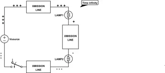
It is helpful to throw away the concept that wires and components behave in an ideal way. We will model the wires as transmission lines. In this case, there will be a voltage wave starting from the last terminal connected. Let's look at each case. Relative voltages are represented with + and -. So from high voltage to low voltage the order is +++, ++, +, -, --, ---.

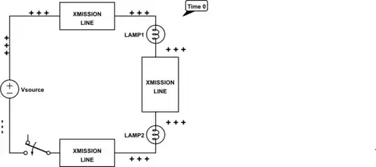
Case 1: ground connected initially

In this case, the circuit nodes are charged to ground voltage initially.

schematic

simulate this circuit – Schematic created using CircuitLab

When the power supply is connected, a voltage wave starts from the power supply terminal as electrons are sinked by the power supply. LAMP1 is the first to have a voltage difference across it, so it will light up first.

schematic

simulate this circuit

Once the voltage wave has reached the ground terminal, a portion of it may reflect back and travel the opposite direction (see ringing). Assuming the absolute value of the reflection coefficient is less than 1, the wave will eventually disappear after an infinite time, and the circuit will stabilize to a constant voltage at each node of the circuit. In practice, the wave should decay to have a negligible effect nearly instantaneously.

schematic

simulate this circuit

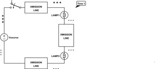
Case 2: power connected initially

In this case, the circuit nodes are charged to power supply voltage initially.

schematic

simulate this circuit

When ground is connected, a voltage wave starts from the ground terminal as electrons are sourced from ground. LAMP2 is the first to have a voltage difference across it, so it will light up first.

schematic

simulate this circuit

Once the voltage wave has reached the power supply terminal, again, a portion of it may reflect back and travel the opposite direction before the circuit stabilizes to constant voltages at each node.

schematic

simulate this circuit

Case 3: both terminals connected simultaneously

Actually, this case depends on the initial voltage of the circuit. If it is in between the power supply voltage and ground, a voltage wave from the power supply will pull (sink) electrons out of the circuit, while a voltage wave from ground will push (source) electrons into the circuit. In summary, its a combination of the two previous cases, with two waves travelling in opposite directions.

Which lamp turns on first?

From the intuition from the diagrams, we know that the bulb closest to the switch will light first. The lights might switch from off to on just once, or they may flicker on and off as the voltage waves reflect back and forth across the circuit. They may switch gradually, or very abruptly. The behavior depends on the impedance of the overall circuit. This will determine the sharpness of the voltage waves (gradual vs. abrupt switching) as well as the number and intensity of the reflections (flickering).

You could get into Maxwell's equations and transmission line theory and figuring out exactly which light would turn on at which femptosecond and get super pedantic about it. But why spend years to answer this question, when you can just get the intuition in a few minutes? All you need to know is that voltage, as an electrical potential difference, travels in a wave! That's all you need to know!

travisbartley
  • 4,823
  • 3
  • 23
  • 41
  • @RedGrittyBrick, This is the paper I kept in mind while writing this. It shows how a voltage wave propagates through the transmission line. I am sure other effects make reality deviate even from transmission line theory, but the model should be good enough to answer this question. http://web.cecs.pdx.edu/~greenwd/xmsnLine_notes.pdf – travisbartley Aug 08 '13 at 07:53
  • I misread your answer (because I'm lazy and it is long) so I've deleted my earlier comment. I think your conclusion is that which lamp lights first depends on which side of the battery (in your diagram) the switch is located, so the answer to the OP's Q is that the answer to **"from + to -, [or] from - to +?"** is - **it depends whether the switch is nearest + or nearest -**. – RedGrittyBrick Aug 08 '13 at 08:24
  • @RedGrittyBrick, exactly, it matters which terminal has the switch. I need to make the diagrams smaller so the post isn't so daunting, but I don't know how to. I guess other people have the issue too. http://meta.electronics.stackexchange.com/questions/2716/smaller-circuitlab-schematics – travisbartley Aug 08 '13 at 08:28
  • Yes, the size of circuitlab diagrams in electronics.stackexchange often seems irritatingly huge - much much larger than is needed for clarity - I see this issue was alraedy discussed in [meta](http://meta.electronics.stackexchange.com/q/2716/2191) (otherwise I'd have raised it there). The current solution is tedious - export to PNG and select image width. – RedGrittyBrick Aug 08 '13 at 08:38
  • @RedGrittyBrick, I made the diagrams shorter. Is the answer still too long? Do you think I should take out the diagrams for case 2 since they are just the opposite of case 1? – travisbartley Aug 08 '13 at 08:44
  • 1
    It's a very good answer (upvoted). I'm loth to press you to lavish more time on it but maybe a very short text summary of your conclusion at the beginning might help lazy slobs like me. If you really really really love editing diagrams you might find a more compact layout. Maybe after the first diagram, following diagrams could be unravelled to a horizontal line from Batt+ to Batt- I'm not sure if that would hinder understanding and require too much extra explanation - tell the reader it's done for concision? Just a thought. – RedGrittyBrick Aug 08 '13 at 08:53
  • "We at least know the electrons can't travel faster than the speed of light, so they do have finite speed" suggests that the speed of electrons is relevant here, but it's not. What's relevant in the speed of a *wave in electrons*. The actual [net speed of the electrons is a function of current](http://amasci.com/miscon/speed.html), and for charge density and currents typically encountered, it works out to centimeters per hour, though individual electrons are zooming in random directions at much higher speeds. – Phil Frost Aug 08 '13 at 12:01
  • @PhilFrost, You're right, of course. I only said that to put an upper bound on the propagation speed, to show that it is finite. And the wave propagation speed is limited by the speed of the electron. The actual speed doesn't matter much for my point. – travisbartley Aug 08 '13 at 12:06
  • 2
    @trav1s the speed of electrons does not bound the speed of EM waves. I can accelerate particles of air well beyond the speed of sound; this doesn't make the speed of sound faster. It's also possible to make electrons go faster than the phase velocity of light in some medium, and when you do it, you get a [really neat blue glow](http://en.wikipedia.org/wiki/Cherenkov_radiation). The speed of electrons has little to do with the speed of light. – Phil Frost Aug 08 '13 at 12:17
  • @PhilFrost, I'll think about that, what a mind blaster. I will go ahead and take it out. – travisbartley Aug 08 '13 at 12:22
  • Although what @Phil said is correct, what you had written was (basically) correct also - the speed of electric current *(and everything else)* is bounded by the speed of light. I'm not sure that information is relevant to the answer, though. – BlueRaja - Danny Pflughoeft Aug 08 '13 at 12:40
  • @BlueRaja-DannyPflughoeft I agree, I just thought it was misleading, because the speed of electrons is not the speed of light. In fact, I think all thinking about movement of electrons is usually misguided: the electrical forces we usually care about are fields that exist because we move electrons: the electrons themselves are the medium, not the interesting thing. It would be like a plumber obsessing over the movement of water molecules, neglecting to consider pressures and waves within the pipes. – Phil Frost Aug 08 '13 at 14:03
  • @PhilFrost, I posted a question about this. I know you have solid understanding of it and recognize the common misconceptions so I invite you to post an answer. http://electronics.stackexchange.com/questions/78448/how-fast-does-electricity-flow – travisbartley Aug 09 '13 at 03:56
-1

Assume a lossless conductor with no capacitance/inductance: electrons do not move at infinite velocity, so it is perfectly valid to imagine flipping a switch as slowly inducing a wave of energy that travels down the wire; however, since light bulbs light up when current is flowing, and since current only flows once the electrons start moving, the lights won't light up until the EM field has propagated completely. All light bulbs will light up at the same time.

However! That ideal model is bullshit. In reality, your wires have capacitance and inductance; these will affect the circuit. Imagine the bulbs are wired in parallel. In this case, when you flip the switch (which can be installed at either positive or negative side, the bulb closest to the switch will turn on first.

Jay Carlson
  • 2,819
  • 1
  • 14
  • 21
  • 2
    All but one thing makes sense. The lightbulbs have no "knowledge" of whether or not the entire circuit is complete, only if their part of it is, so if the EM field is halfway done propagating through the lights, then wouldn't those it had passed light up, as they would think that the EM field had propagated? – Tom Aug 08 '13 at 05:44
  • 2
    All bulbs *won't* light up at the same time, even with an ideal, zero capacitance, zero inductance circuit. As the EM field is propagating, electric charge is moving, and this will light the bulbs, even if it isn't done propagating. – Phil Frost Aug 08 '13 at 11:39