Okay I want to make a simple circuit to measure high currents coming from my car battery, and I think I have something that might work, but I'd like anyone who knows more about this to point me in the right direction.
I read car starters can pull hundreds of amps, and so for the sake of this design, I just assumed my car will max out at 200A during ignition. It might be higher, but I have a small car (Ford Escort) and I think if it goes over 200A for a brief bit it will be okay.
My design is to use a shunt resistor to get a reading of the high current.
It's a 200A, 75mV scale shunt from Digi-Key, here.
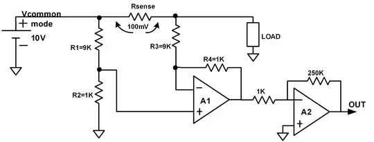
So I want to take the voltage on the shunt, feed it into an op-amp, and scale it to max out at 5V for an arduino. Here's what I came up with.
If you slide the resistance all the way to the left, the load (modeling the starter) will drop to 0.06 Ohms, which is what I'm estimating the starter to be to draw 200A from a 12-V battery. .06 = 12/200.
Then if you slide it to the right, it mimicks normal operation, for current draw for the rest of the car, and will go as high as 12 ohms, pulling 1 amp.
You can see the output of the op amp maxes out at 5V, and the power on the shunt maxes at about 15 watts.
So obviously this circuit design looks like it could work in theory, but what I want to know is if there's a better way to do this? Or if the circuit can be improved? Or if it would even work at all?