3

I just recently started trying out on electronics engineering, and have built a OR gate, NOT gate and a AND gate using NPN transistors. When building the XOR gate, this is my design:

enter image description here

However, SW2 will not activate the LED due to the current at the base of Q4 (activated by SW2) activates Q5 to bypass the LED. Thus, the Q3 & Q4's AND gate does not work. Is there any way I can get the between Q4 and Q5 to not flow unless both Q3 and Q4 have been activated?

Thanks in advance! I'm such a newbie.

P.S. The simulation lets the current flow from the positive side to the negative side.

ihsoy ih
  • 133
  • 5
  • 2
    You're missing more than a couple of resistors. – Ignacio Vazquez-Abrams Aug 02 '13 at 01:59
  • 2
    I don't know what you are trying to say with your comment about the simulation and current flow direction, but it suggests you [have some misconception](http://www.eskimo.com/~billb/amateur/elecdir.html.save) about [how current flows](http://electronics.stackexchange.com/questions/75250/how-is-saltwater-able-to-conduct-electric-charge-between-two-wires). – Phil Frost Aug 02 '13 at 02:07
  • @IgnacioVazquez-Abrams can you kindly tell me which ones I'm missing? We're not learning that yet so I have no idea. – ihsoy ih Aug 02 '13 at 02:22
  • Generally you should have something like 1k in series with each base - although in this case you have 1k in series with _the entire circuit_. I suppose that achieves the goal of overcurrent protection... – pjc50 Aug 02 '13 at 06:47

2 Answers2

1

Conceptually, I can see why you implemented the circuit this way:

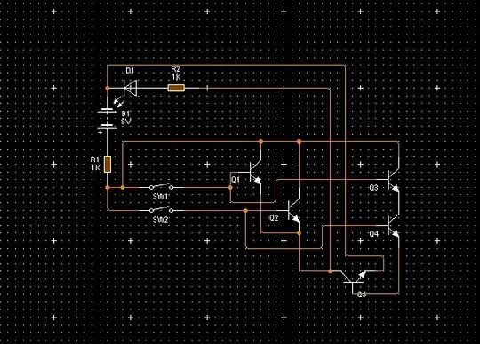
  1. If either of SW1 or SW2 is closed - either Q1 or Q2 will conduct and the current will flow to the LED
  2. However, if both SW1 and SW2 are closed - both Q3 and Q4 will conduct which will cause Q5 to conduct. When Q5 is conducting, there is not enough voltage on LED to turn it on

Good thinking, really.

However, BJTs have high current gain (\$\beta\approx100\$). It means that even a low current to the base of Q5 will be amplified and the LED won't turn on. But how comes there is a current to the base of Q5 when SW1 is open? Isn't Q3 behaves as an open circuit when SW1 is open? The answer is NO - BJT transistors have very interesting behavior when operated with floating base. They are not, in general, behave like an open circuit.

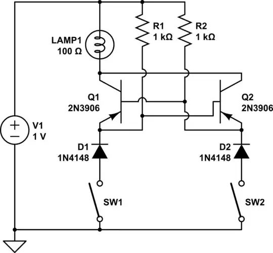
What can you do? Well, in real applications you wouldn't design and use such a circuit. However, given that you are educating yourself (and me too), I'd suggest you try to apply the following changes:

  1. Why did you choose 9V power supply? Each BJT has a maximum rating for \$V_{CE}\$ - check the model file that you're using and change your power supply accordingly. How this may help? Well, reducing \$V_{CE}\$ of Q3 may cause it to behave more like an open circuit when SW1 is open.
  2. Try to add pull-down resistors between bases of Q3 and Q4 and the ground (these resistors must be pretty large). This approach will prevent the base of Q3 from being floating when SW1 is open (respectively for Q4 and SW2).
  3. If none of the above worked, I suggest you'll try to find a way of "stealing" the current from the led which is not that sensitive to small unwanted currents as a single transistor. You may try to replace Q5 with Q3 and Q4 directly (collector of Q3 is connected in place of Q5's collector, emitter of Q4 is connected to ground).

Please let me know about the results.

Vasiliy
  • 7,323
  • 2
  • 21
  • 38
  • Wow, thanks! I used 9v because that's the default. Seems that that was a mistake. – ihsoy ih Aug 02 '13 at 12:47
  • For 1: I put it down to 1.5 volts, and S1 no longer lights up the LED when closed. – ihsoy ih Aug 02 '13 at 13:07
  • For 2: I didn't quite get what you meant by this so I connected two resistors each from each base, Q3 and Q4, to the negative end of the battery. This will result in the same things that happened originally, but if combined with #1, both switches do not light up the LED. – ihsoy ih Aug 02 '13 at 13:10
  • For 3: Both switches do not light up the LEDs. By now I realised I have not gathered enough knowledge to try out these things yet. I'll read a book and come back to it later. Thanks anyway! – ihsoy ih Aug 02 '13 at 13:18
  • 1
    I understand that 1 solved your issue. By 2 I meant exactly what you did - in addition to current circuit, connecting a resistor from a base of Q3 and Q4 to the lowest potential (which I called ground). I understand that this did not help. It is surprising that for 3 you couldn't light up the LED - if you need to debug this circuit further, add the schematic of 3 to the question. Good luck – Vasiliy Aug 02 '13 at 18:41
1

This is my first time trying the built-in editor. Hopefully this works.

schematic

simulate this circuit – Schematic created using CircuitLab

This circuit should behave as an XOR using only two transistors; the circuit is one I designed back in 1977 to control trailer lights (for the left trailer light, one input would be the left flasher and the other would be the brake). Conceptually, this approach should work extremely well within the design of an NMOS chip, though I don't know if any chips actually used it.

supercat
  • 45,939
  • 2
  • 84
  • 143
  • For some reason, this didn't work? BTW, why is there 2 LEDs and a lamp? Wasn't it just supposed to be one LED? Thanks anyway! – ihsoy ih Aug 03 '13 at 02:07
  • 1
    @ihsoyih: The diodes are just diodes--not LEDs, and I mis-drew the schematic the first time. There should just be one lamp. The diodes are necessary to prevent the emitter-base junctions from allowing current from one input back to the other. Not an issue if the inputs are just switches and don't feed anything else, but without the diodes the blinkers would cause the main car's brake lights to go on. Also, I just realized the power supply's a bit low. The original used 12 volts, though 5 would probably work. – supercat Aug 03 '13 at 13:18