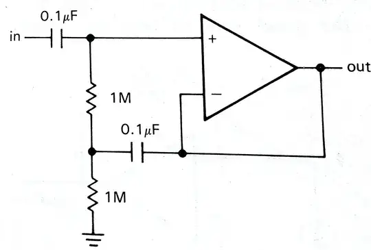
Lets see what we're trying to implement here:
- AC follower (A = 1 for frequencies of interest)
- AC coupled (A = 0 for DC)
- High input impedance
We get the desired results by the following means :
- AC follower - \$V_{out}\$ and \$V_-\$ are shorted
- AC coupled - a series capacitor after \$V_{in}\$
- High \$Z_{in}\$ - bootstrapping
From the first glance it looks like \$Z_{in}=2M\$. Well, you could achieve the same without bootstrapping, so why bother? It turns out that the input impedance of this follower is higher than 2M. In fact, the input impedance in this configuration will (usually) be determined by amplifier's input impedance, and not by the values of voltage divider resistors.
Lets see how it works:
DC is blocked, therefore all the signals in this explanation are AC at the frequencies of interest.
Step-by-step propagation of signals:
- \$v_{in}\$ changes -> \$v_+\$ changes
- \$v_+\$ changes -> \$v_{out}\$ changes
- \$v_{out}\$ changes -> \$v_-\$ changes
- \$v_-\$ changes -> \$v_{out}\$ changes -> back to step #3 above
The only possible steady state in this condition is: \$v_+ = v_- = v_{out}\$.
Up until now I described the basic follower. However, in this configuration there is one addition - \$v_-\$ is also fed back to the upper resistor's second terminal (lets call this resistor \$R_1\$). So, what the voltage at the resistor will be then? In terms of amplifier's inputs it will be:
$$v_{R_1} = v_+ - v_-$$
From the above discussion you may think that this voltage will be zero, but let's not forget that the above discussion is the idealized case. In fact, the gain of the follower won't be exactly 1 - it will be very close to 1, but not 1. What are the implications of this? Well, the voltage on the resistor will be:
$$V_{R_1}=v_+ - v_-=v_{in}-Av_{in}=(1-A)v_{in}$$
Since A is very close to unity, the voltage on the resistor will be almost zero, but not zero. This voltage will give rise to current of magnitude:
$$I_{R_1}=\frac{(1-A)v_{in}}{R_1}$$
What is this current? It is a current drawn from the source by the resistive divider! If we try to express the "effective resistance" of the divider by comparing the above equation to Ohm's law, we will get:
$$R_{eff_{divider}} = \frac{R_1}{(1-A)} >> R_1$$
Given that this huge effective resistance of the divider is in parallel to the input impedance of the amplifier (which is big, but not that big), you can understand why the input resistance of the whole circuit will be determined by the latter.
An answer:
You may notice that I did not answer your question yet. Well, the answer to your question is that a tiny current source is just a way of modeling the tiny current which will flow trough \$R_1\$. It is not really zero, but very close to it. Don't take this too seriously - if you understood the whole explanation I wrote above, don't care about not understanding some alternative (and useless in my opinion) way of describing this circuit.