1

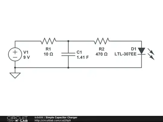
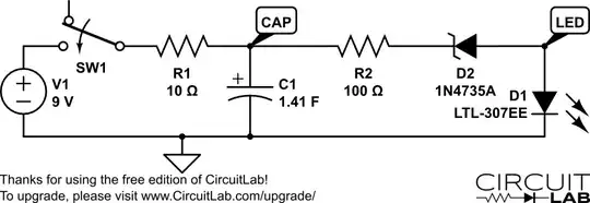
I've built this circuit to charge 3 large, .47F capacitors:

Circuit

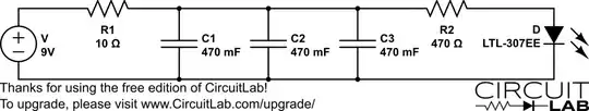
The capacitors are really big, and they charge up slowly. The addition of R2 and D is for D to light up in increasing power as the capacitors charge, and when they are fully charged, D should light up in full power.

However, I didn't manage to get it working correctly. D lights up in seamingly full power when the capacitors are not even half full.

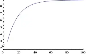
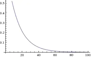
How can I create a V(t), I(t) and finally a R(t) functions for the capacitors? (It isn't an ohmic resistance but you get my point). Using these I'll be able to find proper values for R2 and D, and anyway I'm just intrested in how the voltage is built up.

Iancovici
  • 2,246
  • 17
  • 28
Jong
  • 113
  • 3
  • 047 is not 470 mF. Change to either 470 or 47 mF. – Russell McMahon Jul 30 '13 at 10:56
  • For starters there's no AC signal. You can assume D is a voltage drop of 2 V, combine all parallel capacitors to create a 1.42 F capacitor (capacitors add up in parallel). Then you got yourself got an easy circuit with 2 loop, apply mesh or nodal analysis. Get the differential equations and solve it. – Iancovici Jul 30 '13 at 10:58
  • Have you checked the actual voltage rise curve? LED brightness is far from linear. – pjc50 Jul 30 '13 at 11:00
  • Is your 9V supply capable of providing over 900mA without a voltage drop? If not then you need to include the output resistance of th 9V source in series with the 10 ohm resistor. – Joe Hass Jul 30 '13 at 15:37
  • The power supply is capable of providing 600mA. And the capacitors are 0.47F each, I missed the dot :( – Jong Jul 31 '13 at 08:49

3 Answers3

3

Time constant \$= \tau = RC\$.

\$ R = 3 \cdot 470 mF\$ (based on one of two values you give) so:

$$\tau = 10 \cdot 0.47 F \cdot 3 \approx 15 \text{ seconds}$$

That is one exponential time constant or about 65% of full. Each successive time constant fills it about another 65% of the remaining voltage.

However, the LED (assume \$V_{operate} \approx 2V\$) has a current drain of:

$$I = \frac{V}{R} = \frac{V_{cap}-V_{led}}{R2} \approx 2 mA$$

about \$2mA\$ per volt on caps above 2 volts. So, about \$2 mA\$ at \$3V\$, \$6 mA\$ at \$5V\$, or \$10 mA\$ at \$7V\$.

Light level between \$3V\$ and \$7V\$ is about 10 mA : 2 mA = 5:1 but your eye sees it as a much lower range than that. You need a means of delinearising LED response or, easier, using some other indicator. A bar graph voltmeter or a small analog meter would do a better job for you.

LM3914 based bar graph voltmeter
And similar

Phil Frost
  • 56,804
  • 17
  • 141
  • 262
Russell McMahon
  • 147,325
  • 18
  • 210
  • 386
2

Like echad said, combine the capacitors in parallel first and you'll end up with this circuit:

Capacitor Charger

Next, just you can use mesh or node analysis. Here is node analysis.

Node 1

$$I_1 = I_2 + C \cdot \frac{\mathrm{d}V_c}{\mathrm{d}t}$$

$$I_1 = \frac{(9 - V_c)}{10}$$

$$I_2 = \frac{(V_c - 2)}{470}$$

So:

$$\frac{(9 - V_c)}{10} = \frac{(V_c - 2)}{470} + C\cdot \frac{\mathrm{d}V_c}{\mathrm{d}t}$$

Solve this and it becomes:

$$1.41\cdot\frac{\mathrm{d}V_c}{\mathrm{d}t} + 0.1021\cdot V_c - 0.9046 = 0$$

Then solve the differential equation and you find:

$$V(t) = 8.86 - 8.86 \cdot e^{-0.0724 \cdot t}$$

Now if you want an equation for the current, already used was:

$$I = C\cdot\frac{\mathrm{d}V_c}{\mathrm{d}t}$$

So derive the equation for $V_c(t)$ and you get:

$$I(t) = 0.90446 \cdot e^{-0.0724\cdot t}$$

Since each capacitor is the same, just divide that current by 3 to get the the current for a single capacitor.

Here is a graph of the voltage on the capacitors versus time:

Voltage vs. Time

Here is a graph of the current through all combined capacitors versus time:

Current vs. Time

And this is consistent with at least 1 simulation:

Simulation

Phil Frost
  • 56,804
  • 17
  • 141
  • 262
krb686
  • 1,215
  • 13
  • 23
1

You can make your LED indicator work much better by adding a zener diode in series with it as shown here. The zener diode prevents any significant current from flowing until the voltage across the capacitors reaches about 8 volts. I've used a 6.2V zener in this simulation but you can choose a higher or lower value.

enter image description here

Joe Hass
  • 8,447
  • 1
  • 29
  • 41