0

I apologize if this type of question doesn't belong here, but I recently completed a circuit diagram for an upcoming project, and realized upon review that I didn't include any resistors... There didn't seem to be anywhere in the circuit that required resistors.

Here is the diagram in question:

Circuit Diagram

Long story short, did I omit something obvious?

Soviero
  • 509
  • 1
  • 7
  • 14
  • 2
    [Style guide for drawing schematics.](http://electronics.stackexchange.com/q/28251/7036) Check it out. – Nick Alexeev Jul 29 '13 at 06:17
  • A small issue: Instead of feeding the positive supply rail for the transistors from the 5 Volt regulator that also feeds the RPi, supplying those transistors (i.e. the C+ contacts in the relays) from the 6 Volt regulator that supplies the motors would prevent (or significantly attenuate) relay switching noise appearing on the RPi's supply. With common ground, there is no benefit to using the 5 Volt regulator for the transistors, unless the relay coils cannot handle voltage greater than 5 Volts. – Anindo Ghosh Jul 29 '13 at 06:24
  • 1
    Do you realize that both voltiage regulators will need cooling? IIRC a PI draws some 500 mA, so the regulator will dissipate 0.5 * 7 = 3.5W. When the motors realy draw 3A that regulator will dissipate 3 * 6 = 18W !! – Wouter van Ooijen Jul 29 '13 at 07:21
  • @WoutervanOoijen That's only if you assume those are linear regulators and not switching regulators. There are many 3 pin drop-in switching reg modules. – Passerby Jul 29 '13 at 07:27
  • if you use a solid-state H-bridge you can dispense with the regulator for the motors and probably save some money over mechanical relays. – Phil Frost Jul 29 '13 at 12:15

1 Answers1

4

You need resistors in series with the base of each transistor. Right now, you're abusing the current-limit of the GPIO pins in the broadcom MCU to limit the base-current to the transistors. This may damage them (it may already have done damage, too).

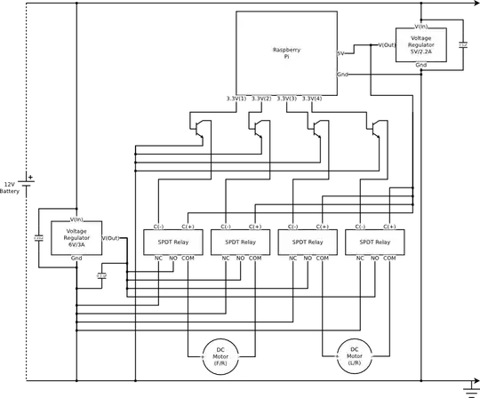
Also, assuming the relays you are using are mechanical, you really should have clamp diodes across the relay coils. As it is, when you turn the relay off, the collapse of the magnetic field will cause a high-voltage spike that may get back into the rPi and damage something, or cause a spontaneous reset/wierd unpredictable issues.

Lastly, I don't know if your voltage regulators are a assembly, or just a bare device. If they're a bare device, you probably need bypass capacitance on the output of the 5V regulator.


Re: The relay diodes:

Take a look at these questions.

Connor Wolf
  • 31,938
  • 6
  • 77
  • 137
  • Would a 1K resistor work for the transistor bases? I've never heard of a "clamp diode" before... Is it anything like a transient voltage suppressor? As far as the voltage regulator goes, I've been following the datasheet, and the 5v regulator didn't require a capacitor between V(out) and ground. – Soviero Jul 29 '13 at 06:18
  • @KevinSoviero Links to the two voltage regulator datasheets, please? – Anindo Ghosh Jul 29 '13 at 06:19
  • @AnindoGhosh 5V regulator datasheet: http://www.jameco.com/Jameco/Products/ProdDS/876221.pdf – Soviero Jul 29 '13 at 06:22
  • 1
    @KevinSoviero From the datasheet: "***Co** is not needed for stability; however, it does improve transient response. Values of less than 0.1 F could cause instability.*" The load is being switched, hence transients will be significant. An output capacitor is rather strongly recommended in such case. – Anindo Ghosh Jul 29 '13 at 06:26
  • @AnindoGhosh Ok, thank you for your help, would a 0.1 uF work? – Soviero Jul 29 '13 at 06:30
  • @KevinSoviero My preferred starting value is a 1 uF or at least a 0.47 uF to start with, then increase or decrease based on how much the transients are affecting output. You wouldn't want front/rear motion to hiccup every time the left/right motor is activated. – Anindo Ghosh Jul 29 '13 at 06:36
  • @AnindoGhosh Thank you very much for the information! – Soviero Jul 29 '13 at 06:39
  • The regulator you link is a 1A regulator. Where did you get the 2.2A/3A numbers on your schematic from? – Connor Wolf Jul 29 '13 at 07:32
  • @KevinSoviero That datasheet is for a standard 7805 Linear Regulator. You will have heat issues with them. – Passerby Jul 29 '13 at 07:34
  • @ConnorWolf that datasheet shows 2.2A max current at 25 degree C junction temperature. It says "in excess of 1A". – Passerby Jul 29 '13 at 07:35
  • @Passerby - Huh, The first line is "1.0 A Positive Voltage Regulators". That datasheet is rather poor. – Connor Wolf Jul 29 '13 at 07:36
  • @ConnorWolf "With adequate heatsinking they can deliver output currents in excess of 1.0 A" and on page 3 electrical characteristics "Peak Output Current (TJ = 25°C) Imax 2.2 A" and page 19 output current graph. – Passerby Jul 29 '13 at 07:49
  • @Passerby Figure 12. As long as you have a heatsink with a theta of 0 C/W you should be able to draw 2.2A indefinitely. If you could share the part number of said heatsink that would be awesome. – Joe Hass Jul 29 '13 at 11:09
  • @JoeHass You couldn't afford it. – Passerby Jul 29 '13 at 11:21
  • @ConnorWolf Would this diode work? http://www.jameco.com/webapp/wcs/stores/servlet/Product_10001_10001_312101_-1 – Soviero Jul 29 '13 at 18:22
  • @KevinSoviero - That should probably work fine. – Connor Wolf Jul 30 '13 at 05:28