8

I'm trying to analyse the circuit below (from Art of Electronics, 2nd edition, p. 96). What are the small signal input and output impedance of this emitter follower? emitter follower with bootstrap

I can analyse an emitter follower, but I'm doing something wrong with the capacitor.

Henk
  • 499
  • 2
  • 7
  • 11

2 Answers2

7

Here's how I would work out the input impedance.

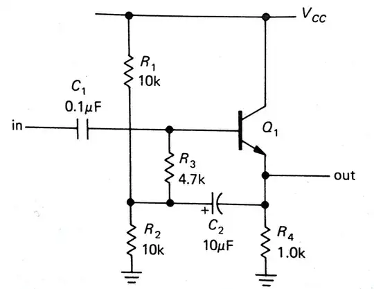
At the frequencies of interest, consider C2 to be a wire.

Note then, that the output voltage appears at the bottom of R3 whilst the input voltage appears at the top.

Let the voltage gain of this circuit be \$A_{CC} < 1\$.

Then the voltage across R3 is \$v_{in} - A_{CC}\ v_{in} = v_{in}(1 - A_{CC})\$

The current through R3 is then \$\dfrac{v_{in}(1 - A_{CC})}{R_3} \$

Thus, to the input voltage source, R3 "looks" bigger by factor of \$\dfrac{1}{1 - A_{CC}} \$

Looking into the base of Q1, the impedance is approximately \$(1 + \beta)\ (R_4||R_2||R_1 + r_e) \$ where \$r_e = \frac{V_T}{I_E} \$.

Then, the input impedance is:

\$r_{in} = \dfrac{R_3}{1 - A_{CC}} || \left[(1 + \beta)\ (R_4||R_2||R_1 + r_e) \right] \$

Since the left hand term in the parallel combination is typically far larger than the right hand term, the input impedance is dominated by the right hand term, i.e.,

\$r_{in} \approx (1 + \beta)\ (R_4||R_2||R_1 + r_e)\$

For example, with \$V_T = 25mV\$ and \$I_E = 1mA\$, \$r_e = 25 \Omega \$ thus, with \$R_4||R_2||R_1 = 833 \Omega \$:

\$r_{in} \approx (1 + \beta)\ 858 \Omega \$

Alfred Centauri
  • 26,502
  • 1
  • 25
  • 63
  • Thanks, I redid the calculation with yours as guide. I get a slightly different answer: \$r_in = (1+β)(R4||R2||R1) + r_e\$, because \$I_c\$ doesn't go through \$r_e\$. Could you check your calculations just to be sure that there is no wrong information in the answer. – Henk Jul 29 '13 at 09:19
  • Instead of relying on the gain you could also put \$R_3 \text{ parallel to } r_e\$, \$R_3\$ is much bigger than \$r_e\$ so \$ r^{'}_{e} \approx r_e\$. – Henk Jul 29 '13 at 09:30
  • @Henk, you may be thinking about \$r_\pi\$ rather than \$r_e\$: \$r_\pi = (1 + \beta)r_e\$ – Alfred Centauri Jul 29 '13 at 10:53
  • You're right, I only knew of the Hybrid-\$\pi\$ model. – Henk Jul 29 '13 at 16:41
  • @AlfredCentauri I have a question. How did you determine that the amplified \$R_3\$ is paralleled by the other impedance block? – OFRBG Aug 09 '15 at 02:22
  • @OFRBG, the impedance looking into the base is in parallel with the impedance looking into R3. – Alfred Centauri Aug 10 '15 at 01:06
1

There is a text on this question for your reference:

https://archive.cnx.org/contents/47311555-728f-4d1d-a5c1-2138ff7e604c@1/ae-lecture5-partd-bootstrapping-and-darlington-pair

The key improvement over non-bootstraped version is to allow much higher input impedance.

TingQian LI
  • 111
  • 2