For an application where you need to parallel transistors and control current in a linear fashion (not switching the transistors fully on and off), BJTs are your best bet. As Olin Lathrop says, the circuit will need to have resistors in series with the BJT emitters to help balance current.
Here is a starting example circuit to show emitter resistor placement.
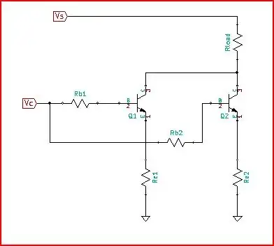
Re1 and Re2 will help balance current between BJTs. The problem is that Vbe has a temperature coefficient (\$\gamma\$) of about -1.6mV/C. As the parts heat up, Vbe will reduce allowing more base drive to the transistor from the fixed value of Vc. With a first order model of Vbe's change with temperature, a simple equation for current in Re1 is:
IRe1 = \$\frac{(\beta +1) (\text{Vc}-\text{Vbeo} (1-\gamma \text{$\Delta $T1}))}{\text{Rb1}+\text{Re1} (\beta +1)}\$
Of course \$\beta\$ will vary with temperature too, but that should be much less important.
Careful choice for Re1, and Rb1 would allow the thermal effect on the current to be reduced. We are talking like 20% kind of numbers here. For example, if Vc=2V, Vbeo=0.7V, \$\beta\$=50, Rb1=10 Ohms, Re1=1 Ohm, and \$\text{$\Delta $T1}\$ increased by 100C over ambient; current through Re1 should look approximately like:
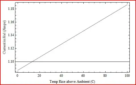
So, with Re1 of 1 Ohm, there is about a 10% change with 100 degrees of temp rise. The emitter resistors in this example would have up to about 1.5W in them. Lower values could be used, but then the variation would be greater. Operation of Q1 and Q2 would mostly be independent except for Vc and voltage across Rload.
To really control the current though would require a feedback loop to regulate Vc. And, to really cause current in each transistor to match would require a feedback loop for each transistor.
Don't Try This With MOSFETS. At least don't expect MOSFETs to magically share current.
While MOSFETs are very good for paralleling in switched mode of operation, they will not share current in linear operation. This is because the gate to source threshold voltage (\$V_{\text{th}}\$) has a negative temperature coefficient. As device temperature rises, \$V_{\text{th}}\$ becomes less, so the warmer the part the earlier it will start to conduct (Micro Semi has an app note about this). Here is a chart of the transfer characteristic to illustrate.
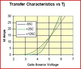
You can see how \$V_{\text{th}}\$ lower as \$T_j\$ rises. This also means that for low drain currents (about 5 amps or so in the chart) transconductance (\$g_f\$) will effectively be higher for the hotter part. Parallel devices will not start to share current until past the crossover point shown on the chart at about 15 amps. It is unusual for FETs operating in linear mode to ever get to the crossover point.
This is even a problem within a single MOSFET. Hot spotting on a MOSFET die is a well known phenomena. If you pop the top of a MOSFET and pull up a microscope, you will see thousands of cells on the die that are parallel micro MOSFETs. Each micro FET has its own \$V_{\text{th}}\$. So, for a fixed \$V_{\text{gs}}\$ and linear operation, the cell with lower \$V_{\text{th}}\$ will start to conduct first and heat up. \$V_{\text{th}}\$ will drop and that cell (and those around it) will conduct more. A hot spot will develop. It is possible for the device to be damaged in this way. On-Semi covers this in app note AND8199 (Hat Tip to Phil Frost).
If sharing between cells on a die are poor, imagine how bad sharing will be between separate devices with not well matched \$V_{\text{th}}\$. Remember how Vbe of the BJT changed by -1.6mV/C? Well \$V_{\text{th}}\$ of the FET changes by about -3mV/C, about twice as much as the BJT. So, current imbalance between paralleled FETs in linear operation will be much worse than BJTs (and they are bad enough).
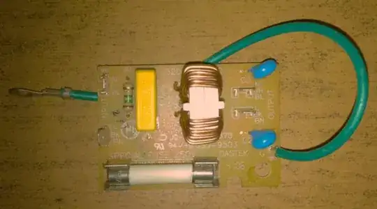
To linearly control current with a MOSFET, \$V_{\text{gs}}\$ needs to be actively controlled by a feedback loop. Here is a recent example of what happens when the MOSFET is not controlled by the feedback loop.
Paralleling linearly controlled MOSFETs for current sharing means having a feedback loop for each device.