3

Did a survey of the commercial products available in the local market, which are broadly classified as 'Automatic Water Level Controller' or 'Automatic Pump Controllers', and found that all of them use a float-switches.

This got me wondering as to why the commercial products do not use 'electrical conductivity' of water as a test, to determine water level in the reservoir. If one uses something like 12VDC of periodic pulse to check for conduction via the electrodes at various levels, there should be no worry of electrical shock. So why don't the commercial systems use this, extremely inexpensive solution ? What is it that I might be missing ?

EDIT

To add a bit of context, what surprised me in my survey was that the price of spare float-switches was about 20% of the price of entire system (including 2 float switches). The cost of installation is about 2x the system price. And every time the float-switch is to be changed there's some labour cost as well (unless the unit is under an Annual Maintenance Contract, which cost 15-20% of the unit price). This is in a rather price sensitive market (India). Which is why the super simple "conductivity" test, seemed like a very cost-effective solution.

jay
  • 258
  • 3
  • 12

3 Answers3

8

Well ... float switches are simple and reliable. Having said that, it is not quite as simple as detecting a DC voltage. Using DC, the electrodes would quickly be corroded (damage due to electrolysis).

The sensing circuit needs to use AC. There used to be a nice IC made by National that would do this, the LM1830N; but as far as I know it is has been obsolete for some time. The circuit is pretty simple to do yourself. Basically an oscillator is connected to a series resistor and capacitor which is connected to an electrode in the fluid. That electrode also connects to a comparator to sense the AC. A second electrode connects to GND (circuit common). When a fluid is present, the conduction between the electrodes causes the AC signal on the oscillator electrode to be attenuated. The resistor sets the sensitivity.

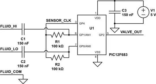
Here is a circuit I built a few years ago using a PIC12F683 :

schematic

simulate this circuit – Schematic created using CircuitLab

This circuit was for a dual-level fluid sensor that would turn on a valve when the fluid would drop below the FLUID_LO sensor, and turn off when the fluid reached the FLUID_HI sensor.

I'm afraid I'm not free to publish the source code, but I will describe the functionality:

SENSOR_CLK is a 50% duty-cycle square-wave output. The frequency is not critical. I used appx 8Khz.

The AN0 and AN1 inputs to the PIC12F683 are inputs to the A/D converter. The conversions are performed when SENSOR_CLK is high. If the voltage is sensed below 3.1V, the corresponding electrode is considered to be immersed in the fluid.

FLUID_HI and FLUID_LO are wires positioned such that they are immersed in the fluid when at the appropriate level. FLUID_COM may either be connected to a metal container holding the fluid, or be connected to a wire in the fluid and below the level of FLUID_LO.

When the wires are immersed in the fluid, the square-wave detected by AN0 and AN1 is attenuated and has a net DC component of about 2.5V. Resistors R1 and R2 may be changed to smaller values if a less sensitive circuit is desired. The 3.1V detection threshold (in firmware) may also be changed to adjust sensitivity, but it must be greater than 2.5V.

While I used the A/D converter in the microcontroller, other detection methods may be used. Some microcontrollers have built-in voltage comparators that may be used. It may also be possible to use general-purpose I/O to detect the immersion when SENSOR_CLK is low if the Vin high and low thresholds are well below 2.5V.

I chose to sense the voltages between the resistors and capacitors instead of the voltages on the electrodes because I felt that the internal clamping diode to VSS in the microcontroller might cause a net DC voltage on the electrodes.

Tut
  • 4,195
  • 1
  • 21
  • 38
  • Thanks @Tut. Clarified my question with a little context. The aspect of "corrosion" is definitely worrying. Since the conductivity test is for a very short duration (say 50 ms) and say 50 odd times a day, should I still expect it to corrode very quickly ? I don't mind replacing electrodes once every 6 odd months, and my neighbour tells me that he's had to change float switches almost once every 8-9 months, since they eventually lose their free-motion. – jay Jul 25 '13 at 19:15
  • @jay There was an answer a day or few ago about this, but I haven't located that question. They mentioned that the corrosion happened very quickly. Probably greatly depends on what else is in the water. Be careful that you could lose some sensitivity as the corrosion occurs. If you can do it, the low-voltage AC method I outlined is much better. – Tut Jul 25 '13 at 19:39
  • In [electrolysis](http://en.wikipedia.org/wiki/Electrolysis) the goal is to apply a DC current, and minimize corrosion on the electrodes. As the (desired, in the electrolysis case) redox reactions occur at the electrodes, the ions thus produced can react with the electrodes, so the electrode material is selected to minimize that reaction. You would have the same problem, just of a lesser magnitude. – Phil Frost Jul 26 '13 at 03:31
  • Thanks Tut and @PhilFrost. The low voltage AC solution increases the system cost somewhat (adding a transformer), but I might experiment with it. Any known material you (Phil) could suggest that might do better as an electrode, with less corrosion ? – jay Jul 26 '13 at 05:45
  • @jay not my area of expertise, but [wikipedia says](http://en.wikipedia.org/wiki/Electrolysis_of_water) maybe platinum, stainless steel or iridium. Researching capacitive water sensing might provide a more robust alternative, and the expense of more complexity. – Phil Frost Jul 26 '13 at 11:02
  • @jay No transformer needed. I built a dual-channel version a few years ago using an 8-pin PIC microcontroller. Very cheap, although the circuit needs a power source of course. – Tut Jul 26 '13 at 12:08
  • Okay Tut. Any chance you might be able to share the schematic ? I am familiar with AVRs, but not that comfortable with analog electronics. What I can imagine is to use 2 digital IO pins, and rapidly toggle between them (50-100Hz?) turning one high (out) and other low (in) with a current limiting resistor in between, and vice-versa. – jay Jul 26 '13 at 14:44
  • @jay Added schematic – Tut Jul 31 '13 at 15:21
3

Water is a poor conductor. If there are salts dissolved in the water, then it's a better conductor, but these salts can then also build up on the sensor as the water evaporates from it, which interferes with the sensor's accuracy. It's also difficult to positively tell the difference between a sensor that is submerged, and one that was recently submerged but is still wet.

Float valves don't suffer from these problems. They work on very pure water or even fluids that aren't water at all. They provide a very positive indication of "submerged" or "not submerged" that is independent of the purity of the fluid being monitored or evaporation. While they introduce mechanical components which may fail, they are widely available and easily serviced by people who may not have advanced electrical knowledge.

Phil Frost
  • 56,804
  • 17
  • 141
  • 262
  • I used to think that it is true for distilled or very pure water. Water stored in reservoir, is somewhat unlikely to be so pure. Also, my idea of conduction test was to have a pair of electrodes that are physical slightly spaced out. Thus them being wet, shouldn't matter unless they are submerged. The gap would be big enough, not to have any direct path between the 2 electrodes (+ve and GND) . The build-up of dissolved salts however, seems like a more likely problem. Thanks for answering. – jay Jul 25 '13 at 19:04
  • @jay even if they are spaced apart, there can be a wet film from one electrode, across whatever is supporting that electrode, to the other electrode. You don't need a straight line connecting the two. Any conductive path will do. – Phil Frost Jul 25 '13 at 19:09
  • Ah, I see your point. – jay Jul 25 '13 at 19:16
1

I realize this is a year old but I was all over looking for answers for an old cooling tower and had this open when I found a place called Waterline Controls that sells 'electronic sensors' (plus software driven controllers that look trick).

They also have good information about all types of water sensors, pros and cons, etc.

They said "Poor water quality can cause the probes to foul, deteriorate or pit, needing to be replaced after one to two years. “Throwaway Technology” with a short life cycle..." ('read more' link goes to www.waterlinecontrols.com/level-sensors/conductivity-probe/).

Their stuff is totally different and well worth looking into if you need a better soulution. They have some major installs listed too, like at google and a nuclear plant, so it certainly works well.

Anyway, hope that helps.

Don
  • 11
  • 1