After having experimented a lot, and read some more, I found an answer to my question.
Simple switch model approach
After seing a demo on the switch models I finally understood the parameters and workings of the SPICE switch model, which I will explain below.
Switch model syntax
.model MODEL SW VT VH RON ROFF
SX N+ N- NC+ NC- MODEL <ON><OFF>
(where a RegEx for X is [a-z0-9]{0,7}.)
What the manual doesn't explain
Although easily guessed:
- The
N nodes are the controlled nodes, which will be "short-circuited" or "opened" (continue reading for quoting reason.)
- The
NC nodes are the controller nodes, from which the "switching" voltage will be read.
The switch is essentially on when the voltage accross the controlled nodes is positive, and off otherwise, this is also easily guessed.
Now, the hysteresis voltage makes it possible for the user to define a "dark voltage interval", in which the switch will not be able to change its state. This interval is defined by [VT-VH, VT+VH], and is what provides hysteresis to the model. This is interpreted as follows:
- A voltage over
VT+VH will turn the switch on.
- A voltage below
VT-VH will turn the switch off.
Because these are the only conditions ruling the model, the model needs an initial on or off state if the initial voltage across the controller nodes is within the dark voltage interval. This initial state is optional otherwise, for it would be overridden.
The current controlled switch model is analogous to this one, but take note about that between the controlled nodes there is a short circuit.
Sample circuit
Voltage controlled switch

V0 1 0 SIN(0 12 2 0 0)
S1 1 2 1 0 simpleswitch OFF
R2 2 0 10

.model simpleswitch sw vt=0 vh=6 ron=0.1 roff=1Meg

.control
tran 1e-3 1 uic
plot v(2)/10.1 v(1)/10.1 $ voltage/(resistor resistance + switch on resistance)
.endc
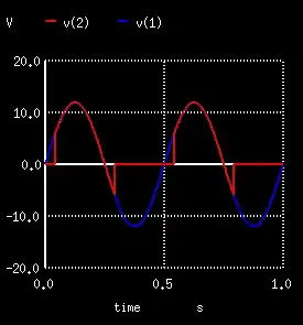
Above you can see the plot resulting from the simulation of the circuit source code. The blue curve corresponds to the source voltage, the red curve to the voltage across the resistor.
As it can be observed from the code, the so called dark voltage interval is [-6,6], at which the switch does nothing (remembers its last state). As soon as the voltage across the controller nodes is over 6 V, there is a current flowing through the resistor (and thus non-null voltage across it); as soon as the voltage is below -6 V, the current flow is cut.