6

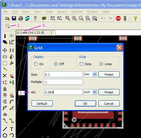
I am using Eagle CAD to lay out a BGA based PCB, for manufacture at Laen's prototyping service. One of the problems which I am having is that BGA parts are typically specified using metric units (for example the ball pitch is .8 mm), but that several other parts on the board (and actually the specifications for the PCB DRC) are given in Imperial units (for example, the minimum trace width is 6 mils, and the minimum hole size is 13 mils).

How do people reconcile the differing systems? For example, if I route things on a metric grid, connectors which have .1 inch spacing no longer align nicely to the grid. Alternatively, if I use a mil grid, I cannot place a via precisely in between 4 BGA balls.

Zuofu
  • 4,168
  • 2
  • 21
  • 36
  • It's not a big deal - it doesn't look perfect but then what does? I suppose the big issue is keeping to design rules that are in mils while routing between balls. On one system I figured out beforehand what I needed to bring out from inner balls and made the footprint for that device with these extansions brought out. – Andy aka Jul 21 '13 at 17:59
  • In practical terms, you just have to deal with it (although SMD was supposed to be all metric from, what, 1985?). Almost all small SMT stuff is in mm. 0.4, 0.5, 0.65 etc. The stuff that isn't tends to be larger - 1.27mm (50 mil), 2.54mm (100 mil). Personally, I round some large items (few enough). Most of the time I switch grid. But, even if the pin is off grid, (I believe) Eagle will help you line it up. It seems to work out most of the time! – carveone Jul 21 '13 at 21:04

2 Answers2

7

This is to further elaborate @ThePhoton's answer.

Eagle supports one alternative grid. It's activated when the Alt key is pressed and held down. The alternative grid is configured in the same dialog as the main grid.

  1. Brings up the grid dialog
  2. Configure the alternative grid
  3. This displays the grid size, which is applied at the moment

enter image description here

Nick Alexeev
  • 37,739
  • 17
  • 97
  • 230
5

I don't know Eagle specifically, but if it's like the tools I know, it has a "hotkey" to quickly switch back and forth between units. And another hotkey to switch grids.

What's usually done is to set up two (or more) grids, and use the hotkey to switch between them. While routing the BGA, use the metric grid. Once you get your line routed out of the BGA region, hit the hotkey to switch to the imperial grid. Jog the line over to the new grid, and route it wherever it needs to go.

Most layouts aren't routed strictly on a grid anyway. You can just route lines as close as the design rules allow, without worrying about a grid (assuming low speed digital signals, where you aren't worried unduly about cross-talk). Some tools have special routing modes to make this easier, for example by having a new line follow an existing one. Or by "shoveing" the old line out of the way to make just enough room as you route the new line.

The Photon
  • 126,425
  • 3
  • 159
  • 304