I thought, I will not bother any more with this project of mine, but I really run out of ideas trying to get it to work.
When using breadboard, the design works as expected (did it couple of times already), however, when I put it onto universal (3-track) PCB, it stopped to work.
I divided the testing into two parts: disconnected R8 to see if U1b generates sound. It does not. The breadboard setup was quickly done using the same pins and yes, it worked right away.
What I have done:
- List item
- measured "voltages" on 8, 9, 14 and compared (I am aware this is oscillating, so values are averages, I guess). Values were very similar.
- touching pin 8 by finger actually produced repetitive sound on the PCB solution, while on the breadboard counterpart it added noises, otherwise reaction was similar.
- checked if C1 is not shortcut, and trying another capacitor
- U1a part also did not work, but I have not researched it extensively.
- of course, checked continuity of all junctions and checked the schematics, more than once
The question is, what else can I try to pinpoint the problem or is it time to rework, for example, get IC out and check if it's still good? (I think, I was very careful and quick soldering IC with 350 deg.C iron, but...). I do not have an oscilloscope yet.
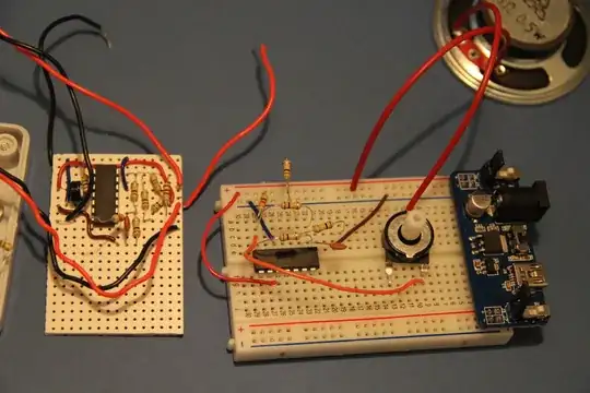
The picture of the board and breadboard is more an illustration, as connections aren't seen. The breadboard implements only oscillator part, but at prototyping stage I had both.
UPDATE: Solved by adding more resistance to Rload, thanks to Rafal Powierski.
UPDATE2: Datasheet for the comparator also advices to connect unused inputs to ground, as Spoon suggested.