So what is the voltage output of that GND pin ? Is it 0v ?
'GND' is the circuit common, the datum, the reference node, or more colloquially, it's the node where you put the black lead of your voltmeter.
In other words, it is the node to which all other node voltages in the circuit are referenced.
It is not a voltage output. The 'GND' pin does not output 0V.
Think about it. If you want to measure the voltage on the 'GND' pin, you would put the red lead of your voltmeter on that pin. Where is the black lead connected? It's connected to the very same pin. So, with both leads of the voltmeter connected together, you read 0V.
When you connect a 5V power supply, the 5V is the voltage across the two power supply leads. When you connect the more negative lead to the 'GND' pin, and the more positive lead to the '5V' pin, you're placing 5V across those two points in the circuit.
Similarly for the 3.3V power supply.
It is often the case that we need two (or more) isolated reference nodes, i.e., 'GND1' and 'GND2' or perhaps "digital ground" and "analog ground". Sometimes, this is for safety, and other times, this is for, e.g., isolation of noise so to reduce interaction between sub-circuits.
And what is the different between GND and Earth ?
The 'GND' node in a circuit is just like any other node. It just that it is, by convention, the 0V node.
'Earth', on the other hand, is an actual physical connection to the Earth via, for example, a long copper rod driven several feet into the soil.
"Earthing" is important in, for example, radio transmission where one lead of the transmitter is attached to an antenna and the other is connected to the Earth.
There's much more that can be said about this but it may be more than you want to know.
To emphasize the essential arbitrariness of the GND node, consider two circuits identical in every way except for the arbitrary choice of the reference or GND node. The voltage across and the current through each circuit element are unchanged by this choice as can be verified by KVL, KCL and Ohm's Law.
The changing of the reference node is no different from changing the location of the reference lead of your voltmeter.
If you place the reference lead between the two voltage sources, the voltmeter will read the following node voltages:
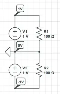
If you place the reference lead on the negative end of the bottom voltage source, the voltmeter will read the following node voltages:
Again, the circuit operation has not changed. Changing the location of the reference lead of your voltmeter will not change the operation of the circuit. But, it will change the readings you get!