4

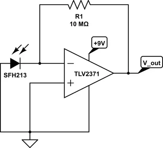
I have been playing with a SFH 213 photodiode (the clear one) and I've hooked it up to a TLV2371 op amp so as to resemble an ordinary transimpedance amplifier.

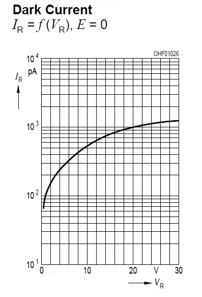
I've varied the feedback resistor value from 10M-30M and still I get zero voltage from V_out. According to the data sheet for the photodiode the dark current is 1(<5)nA so I figured with 10M resistor I would get 10-50mV at the output.

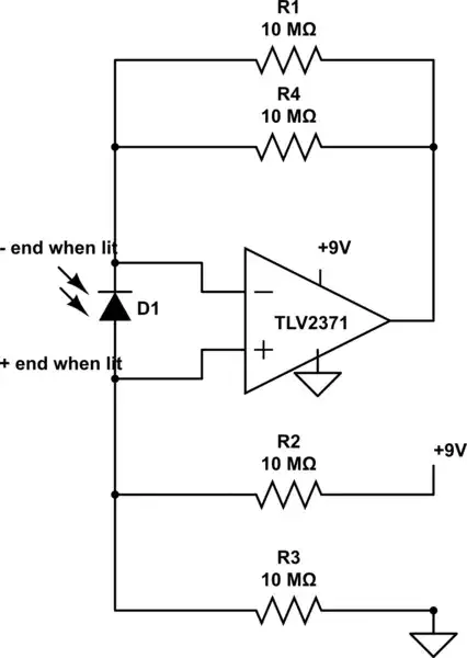
I've tested other configurations with the op amp such as a non-inverting amplifier and it works just as expected. So I don't think the op amp is broken. I also hooked up 2 photodiodes (parallel) in case the one I was working with was broken and to make the signal stronger but still no output. The flat side of the diode is facing pin 2 (-in) and the round side is in pin 3 (+in) which is grounded. The +9 Vcc for the op amp is completely arbitrary value.

I feel like it's a simple issue and I feel silly for asking. However I just can't figure out what's wrong.

schematic

simulate this circuit – Schematic created using CircuitLab

mphommal
  • 65
  • 1
  • 1
  • 7
  • It is generally a good idea to share a schematic instead of a word-picture of the circuit configuration. Pressing `Control-M` while editing your post brings up the integrated schematic editor. If you have insufficient reputation on this site to post a schematic, upload one to any public image sharing site, and add the link here as a comment: Someone with edit rights would then incorporate it into your question. – Anindo Ghosh Jul 15 '13 at 15:40
  • Thank you for that. I was going to upload an image but yes I don't have enough reputation. I will include a schematic. – mphommal Jul 15 '13 at 15:42
  • You should now have sufficient reputation. – Anindo Ghosh Jul 15 '13 at 15:43
  • 1
    The datasheet dark current is specified with VR = 20 V, where your circuit applies 0 V, so I wouldn't expect to see the same value. In fact, with 0 V applied, I'd expect to see essentially 0 dark current, just like in any other diode with 0 V applied. Have you tested actually applying an optical signal to the PD? – The Photon Jul 15 '13 at 16:14
  • I see. I'm new to reading datasheets and all this fun stuff so I guess I overlooked that. The only light incident on the PD is ambient light from the fluorescent bulbs of the room. My intended application won't allow another source of light besides that. However, I plan to apply an optical signal that the PD is sensitive to when I have time just to see what happens. – mphommal Jul 15 '13 at 16:23
  • If your application doesn't use any light that the PD is sensitive to, why do you have the PD in your system at all? – The Photon Jul 15 '13 at 16:27
  • Well, from what I believe, the PD can detect a certain wavelength emitted from the fluorescent bulb. I'm trying to use the PD to detect the difference between a black and white surface which I assume reflects more or less of that specific wavelength of light. Correct me if I'm wrong (which I usually am). – mphommal Jul 15 '13 at 16:37
  • While the sensor will have some response in the 400-600 nm range where fluorescents emit, there's other reasons I don't think you've picked a good sensor for that application. See the graph of "directional characteristics" on the datasheet. This sensor is meant for cases where you are able to aim the sensor at a bright source (like fiber optics or free-space IR). Couldn't you use an ordinary CdS cell here? – The Photon Jul 15 '13 at 17:52
  • It actually wasn't my choice what components I can be using to implement what I'm trying to do. I'd also be lying if I said I completely understand what that graph says but I will look more into it. Thanks for your input. – mphommal Jul 15 '13 at 18:04
  • Try the circuit at http://designtools.analog.com/dt/photodiode/photodiode.html. It provides a Vref to set the op amp comfortably in its working range and provide reverse bias to the photodiode – Scott Seidman Jul 15 '13 at 19:03
  • I removed this link from Andy's answer because my comment no longer applies. Your circuit is also discussed in this previous question: http://electronics.stackexchange.com/questions/36086/does-this-photodiode-circuit-work?lq=1 – The Photon Jul 15 '13 at 20:34
  • @ThePhoton You are right. My PD is more suited for applications that require a bright source. I will see to it that I get a different photodiode or just use a phototransistor (less headaches for me atm). In the mean time I'd still like to try to make this work if possible. – mphommal Jul 16 '13 at 15:06
  • @ScottSeidman I will see if this will fix my issues. Thanks for your suggestion. – mphommal Jul 16 '13 at 15:06

3 Answers3

4

The way you're checking your circuit is not appropriate. The dark current specified in the datasheet is for 20 V reverse voltage applied. However your circuit does not reverse bias the photodiode.

The datasheet shows typical dark current vs reverse bias:

enter image description here

With no reverse bias, you should expect 0 dark current, as in any other diode with 0 V applied.

You need to test your circuit with some light applied to the photodiode. An input signal on the order of 10 to 100 nW (depending on wavelength) should produce a measurable output signal. Be aware that your photodiode has a strongly directional response, and the input light must be entering from nearly "straight on" to be detected. This will limit your ability to detect diffuse reflections.

The Photon
  • 126,425
  • 3
  • 159
  • 304
  • I replaced all my parts and redid the circuit with an effective IR light source and got it working fine. Moving forward, I will reconsider if this PD will be acceptable for my implementation. Thank you. – mphommal Jul 17 '13 at 17:42
1

I'm redoing this answer because I misread the direction of the photo-diode when I first answered but, the circuit still won't work until the light-intensity hitting the photodiode can generate sufficient voltage across the device to help the op-amp.

For the op-amp to work in it's linear region it has to have its two inputs at very nearly the same voltage. I'm talking about within a couple of milli-volts for this device and most others.

To be able to get the Vin- input close to the Vin+ input (at ground), the output will have to swing down to the negative rail. Despite this op-amp being rail-to-rail, it's output won't swing down to ground - the lowest it will reasonably get is +50mV above ground.

Can the photodiode help? Well, after several reads on links provided by @ThePhoton I believe it can help but, only when the light intensity is sufficient.

The photo-diode in the circuit can only help if it is able to provide a negative "pull" on the Vin- input. It needs to pull negatively so that the op-amp's +50mV output to ground offset is countered. It's configured the correct way to achieve this but how much light does there need to be across the device? Well, it's difficult to say but I suspect there isn't enough to counter the 50mV required.

The device is "tuned" to 850nm and progressively excludes all other light outside this range, being 10% efficient at 400nm and 1100nm.

To check that this is correct I'd ask the OP to put a voltmeter across the photodiode to see what open circuit voltage can be measured. This should confirm my "latest" suspicion.

Andy aka
  • 434,556
  • 28
  • 351
  • 777
  • @Andyaka It works even with plain old LMV324 op-amps and single supply. I haven't analyzed why, so I have no explanation to counter your surmise. I'd breadboarded one such set-up using a regular LED as my photodiode, and it worked fine for transmitting Morse code. Worth trying for yourself. – Anindo Ghosh Jul 15 '13 at 19:42
  • I removed my previous comments because they no longer apply. – The Photon Jul 15 '13 at 20:35
  • @AnindoGhosh The LMV324 (Fairchild) o/p can get down to 13mV (typ) on 5V supply. The OP's device can do 50mV (typ). Both have about a 2mV offset so clearly the LMV324 is better equipped to work in this circuit. The LMV is potentially 11mV away from being linear! The TI part is 48mV away - that could be an awful lot of ambient light needed to catch up with the LMV. – Andy aka Jul 15 '13 at 21:18
  • Since you asked I measured the voltage of the PD to be 290mV (120mV less light). I tested the PD using an IRLED and it works as expected with a significant increase in current. However, adding the PD to my original circuit with IR light incident orthogonal I still have no output. I will follow the suggestions of others and alter my circuit. – mphommal Jul 16 '13 at 15:04
  • @mphommal can you measure the output voltage of the op-amp. I suspect it is greater than +300mV above ground for this not to work. You are using a TLV2371 aren't you? – Andy aka Jul 16 '13 at 16:01
0

I'm guessing it's one of 4 effects, all of which are avoided by the following schematic:

  1. No op-amp can drive its output all the way to its power rails.
  2. If you're at all like me, Murphy's law has already kicked in and I've got the leads to the light sensor swapped the wrong way around. (It is not possible to see the difference between an op amp driving its output to GND when dark, vs the op amp "trying" to drive its output to some voltage below its negative power rail when light -- see #1).
  3. Many op-amps don't work well with the inputs very close to their power rails.
  4. All op-amps have at least some bias leakage current.

schematic

simulate this circuit – Schematic created using CircuitLab

I use Dieter Knollman's design procedure because (a) it is simple, and (b) it properly balances the inputs so most of the bias leakage current is cancelled out.

With this circuit, I expect the output to be roughly the same as the + input (about 4.5 V from ground) when the sensor is dark.

With this circuit, there's a pretty good chance that the output will go down (towards GND) when I pull the cover off the light sensor. That tells me that I've switched the 2 leads on the sensor.

If you're at all like me, eventually you hook diodes up to GND and +9V just to see what will happen. Alas, it's pretty disappointing -- the part that was formerly a diode looks exactly like it always has, but internally it is immediately and permanently destroyed.

Dieter Knollman. "Designing with op amps: Single-formula technique keeps it simple".

davidcary
  • 17,426
  • 11
  • 66
  • 115
  • Did you check the datasheet the OP linked to? His op-amp has input bias current measured in picoamps. And a rail-to-rail IO spec that should be adequate for this circuit, given just a few 10's of nW of optical input signal. OP also gave enough information to determine if he has his diode installed backwards. – The Photon Jul 16 '13 at 18:16
  • @ThePhoton: Good point, I see now that op-amp has excellent specs. Alas, I occasionally put parts in backwards even when I know which way is right -- so "enough information to determine if he has his diode installed backwards" is irrelevant. – davidcary Jul 17 '13 at 14:15