0

Background:

I'm working on a project that needs to accurately and quickly measure the rotational speed of the engine in my car. It is a MK3 Ford Focus, and each spark plug has a coil-on-plug that has three wires going to it from the ECU. They are signal, +12v, and ground. When the ECU wants to fire one of the plugs, it sends a +12v pulse on the signal line. The frequency of the pulse is going to be something between 0 and 100hz (ish).

Question:

What is a circuit that I can use to:

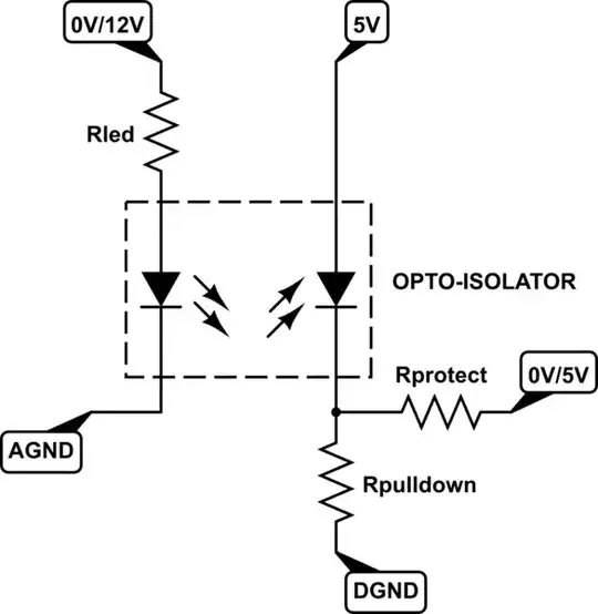
1) clean up the noise on the pulse, as it is pretty noisy.

2) Drop it to something that a) won't kill and b) can be detected by an AVR/Arduino/etc.

Is there any relatively simple way to do this?

  • Look up the Megasquirt project before you duplicate too much effort - they also publish schematics for doing exactly what you need. Also, for general automotive stuff, this may give some useful info on the automotive environment: http://electronics.stackexchange.com/questions/73857/detect-car-12v-using-arduino/73875#73875 – John U Jul 11 '13 at 08:58
  • While it's an interesting project, nowhere does it have what I need. I'm trying to read RPM via the spark lines, not the RPM sensor. Looks like MegaSquirt has no support for electronic ignition (spark), only EFI(gas). – Matthew Kennedy Jul 11 '13 at 20:47
  • You didn't read very far then. The MS-Extra firmware supports many ignition systems. I would say that reading RPM from the coil is not an optimal way of doing it - they're electrically noisy and only fire once per cycle. Reading the RPM sensor, or even the alternator's W terminal as many diesel cars RPM gauges do, will give you a better result (more pulses per rev = better resolution). – John U Jul 12 '13 at 08:15
  • You are looking for the PIP/SPOUT signal and it should be a square-wave. – Jon Feb 23 '15 at 21:01
  • @MatthewKennedy, SPOUT(s) may be adjusted digitally by the ECM correcting for engine load, dwell, etc. The PIP is a single, rather-clean, square-wave signal coming from the distributor/PIP/camshaft position sensor. – Jon Feb 23 '15 at 21:44
  • Quickly and accurately, while using an AVR? I'd epoxy a small permanent magnet to the crank pulley and mount a hall-effect sensor near it, powered from the AVR circuitry. Total isolation, purpose-built design (so you know it will work and not interfere with any other circuitry), and depending on your AVR code, almost instant response. Less slow FP math, no errors from mis-firing, etc. – rdtsc Aug 12 '15 at 16:11

1 Answers1

2

This is galvanically isolated and will mimic the 12V signal at any* Vin.

schematic

simulate this circuit – Schematic created using CircuitLab

The camshaft position sensor (using any technology) outputs a pulse at EVERY firing.
CurrentWidthBetweenPulses = 1.0 / (RPM * NumberOfCylinders / 60.0)
RPM = ((1.0 / CurrentWidthBetweenPulses) * 60.0 / NumberOfCylinders)
RPM = ((1.0 / 0.015ms) * 60 / 8) = 500RPM
RPM = ((1.0 / 0.010ms) * 60 / 8) = 750RPM

Jon
  • 742
  • 3
  • 12