You are likely to have two problems with this sensor:
- it has a very high output impedance (\$1M\Omega\$) and so can not supply much current
- it will change very slowly as it transitions from "wet" to "dry", but you likely want your buzzer or or off, not something in between.
Consequently, you want to measure the resistance with a high input impedance. And, you want something with a whole ton of gain, and perhaps some hysteresis, to keep the buzzer definitely in an on or off state.
There is a device that is cheap and available that does both these things: the comparator. LM339 is a very common variety. Comparators can also be made from discrete components, although it's usually more expensive to do so.
The comparator has two inputs, compares them, and outputs high or low based on which is greater. By connecting your resistive sensor through another resistor, forming a voltage divider, and measuring the voltage in the middle with the comparator, you can distinguish between wet and dry:
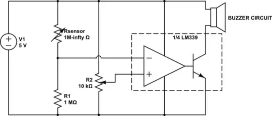
simulate this circuit – Schematic created using CircuitLab
Adjust R2 so that at the threshold you wish to detect, the voltage between R1 and the sensor is the same as the voltage at R2's wiper. You can also change R1.
Since the LM339 has an open collector output, you can conveniently use it to switch power to your buzzer circuit, provided you don't exceed the \$16mA\$ of current specified in the datasheet. If you need more current, follow it with another transistor.
If you still find that the circuit doesn't transition cleanly between on and off, adding hysteresis between the comparator and the buzzer may be the solution. A Schmitt trigger is a common circuit that does just that. 74HC14 is a common variety, or it can be built with discrete components or even the other 3 comparators in the LM339 with examples easily found on the web.