A 3-µF capacitor charged to 100V is connected across an uncharged 6-µF capacitor. So the initial stored energy is: 15mJ and the final: 5mJ. What happen to the 10-mJ of energy?
Asked
Active
Viewed 2,180 times
7
-
[Can a charge-pump be 100% efficient, given ideal components?](http://electronics.stackexchange.com/questions/54992/can-a-charge-pump-be-100-efficient-given-ideal-components) [Energy Loss in Charging a Capacitor](http://www.smpstech.com/charge.htm) – Phil Frost Jul 10 '13 at 11:15
6 Answers
6
This problem is a classic and it provides a wonderful example of the limitations of ideal circuit theory.
There are three assumptions underlying ideal circuit theory and one of those assumptions is, essentially, to ignore the self-inductance of the circuit.
But any circuit (closed path) has inductance. So, even if we keep the idealization of zero resistance wire and ideal capacitors, we cannot escape the fundamental inductance of the circuit (unless we shrink the circuit to zero size).
A careful analysis will show that, even if the resistance is zero (or effectively so) so that there is no effective resistive loss, there is energy "lost" to the electromagnetic field; the "lost" energy is radiated away as electromagnetic radiation.
A detailed derivation can be found in A Capacitor Paradox.
Alfred Centauri
- 26,502
- 1
- 25
- 63
-
-
For a 3µF and 6µF caps to hold the same combined charge and stored energy as they would when charged to 100V and zero 0V, respectively, they must either hold 100V and 0V, or -33.3V and 66.7V. In any other state, they will either hold a different amount of charge or a different amount of energy. One could view a two perfect caps, perfectly connected, as having a state which will alternate between the two indicated conditions "infinitely fast" as long as the perfect connection remains. That would be the limit of behavior in the presence of lossless inductance but no resistance... – supercat Mar 25 '14 at 20:31
-
...assuming the connection was only opened at a moment when the inductor's stored energy was zero. With non-zero inductance, the speed of oscillation would be finite, but provided the connection remained perfectly closed whenever the inductor's energy was non-zero the existence of other states during which the inductor's energy was temporarily non-zero wouldn't affect the state of the system once the connection was cleanly broken. – supercat Mar 25 '14 at 20:32
5
It is dissipated in the non-zero resistance of the connecting wires. You can calculate that the dissipation does not depend on the actual resistance, so reducing it does not help.
related: energy in capacitors (there must be more but I can't find them)
Wouter van Ooijen
- 48,407
- 1
- 63
- 136
-
@ Wouter van Ooijen So is it wrong to say that, the energy disapeared in spark? – user7777777 Jul 10 '13 at 07:06
-
Which spark? If there was a spark (you did not mention one) that will of course have dissipated some energy. But that spark was also part of a (obviously not zero ohm) path, so might as well say that it was dissipated in the conducting path between the capacitors. – Wouter van Ooijen Jul 10 '13 at 07:26
-
I'm not satisfied with this answer Wouter. I think Jim's hits the spot although I do realize that in practice, unsustainable currents will flow!!! – Andy aka Jul 10 '13 at 09:58
-
1@Andy: sadly, nature is not obliged to comply with our intuition. For any non-zero resistance Jim's answer is wrong. – Wouter van Ooijen Jul 10 '13 at 10:12
-
@WoutervanOoijen Yeah I've been thinking about it and it doesn't add up. I feel a simulation is necessary!! – Andy aka Jul 10 '13 at 10:22
-
-
I checked with a simulator and this agrees with your answer - for a very small value of resistance, the peak current is massive and the energy taken from the circuit by the resistor's heat is 7.5mJ (This was with 2 x 3uF caps not a 3uF and 6uF). Lowering the resistor or increasing it does exactly the same - 7.5mJ lost forever!! – Andy aka Jul 10 '13 at 11:11
5
As Wounter van Ooijen has already said, it is a matter of parasitic resistance, which is always present. The proof:
EDIT: Even though the answers provided must satisfy any engineer on this planet (joke), it looks like the case of zero resistance wires is still being considered as a scenario of possible violation of conservation of energy (joke).
In fact, a complete answer to this question must address the case of zero resistivity because everyone heard of superconductors. Well, turns out that the same questions have already been asked at Physics forum. One of the best answers may be found here.
-
The textbook I read from said: "The resistor will,however, slow the time taken for the voltage to reach its final value, which time is five time constants after the switching. This time is zero if the resistance is zero." Does it mean that resistor must always be add to the circuit, for avoiding this "jump" in voltage (because according to the book the time **is** zero)? – user7777777 Jul 10 '13 at 09:44
-
1You don't need to add the resistor, it will be present. Without any resistor, the circuit can not be analyzed at t=0 (the moment you connect the capacitors): what would the current be? – Wouter van Ooijen Jul 10 '13 at 10:14
-
@Wouter van Ooijen Thank you very much! Is it valid to say that the time is zero for voltage to reach its final value with no resistor? – user7777777 Jul 10 '13 at 10:26
-
1With some handwaving that is correct. The more accurate statement would be that for the resistor approaching zero any non-100% criterium for final will be reached in a time similarly approaching zero. (The 100% ciriterium will *never* be met for a non-zero resistance, so it does not make much sense to use it.) – Wouter van Ooijen Jul 10 '13 at 10:50
-
1@user7777777, I edited my answer in light of your further interest in a zero resistivity conductors. Follow the link - there is very interesting thread on the other side. Hope this helps – Vasiliy Jul 10 '13 at 11:25
-
@Vasiliy Zukanov Indeed it helps, thank you very much for your help! – user7777777 Jul 10 '13 at 13:00
-
@user7777777, you welcome. You can also accept my answer if you think it better answers your question, although the answer by Wouter van Ooijen is correct. – Vasiliy Jul 10 '13 at 17:11
3
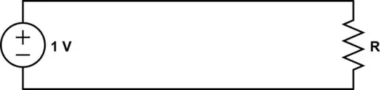
Intuition would tell us that if we could somehow connect the capacitors with a zero resistance, than the energy would be conserved. But this is wrong. Our intuition comes from the fact that usually power decreases as resistance approaches zero. For example:
simulate this circuit – Schematic created using CircuitLab
$$P = 1A\cdot V\\ V = 1A\cdot R$$
Therefore, as \$R\to 0\Omega\$, then \$V\to0V\$. Clearly, \$1A\cdot 0V = 0W\$, so we can say:
$$\lim_{R \to 0} (1A)^2R = 0W$$
This is the usual case because although the circuits we make aren't just current sources, they have some resistance somewhere that limits the current. Thus, we are in the habit of thinking minimize unintentional resistance to minimize loss.
Another example:
$$ P = 1V \cdot I\\ I = 1V/R $$
Therefore, as \$R\to 0\Omega\$, then \$I\$ gets bigger, and then you hit a division by zero. Therefore, we can't evaluate the limit:
$$\lim_{R \to 0} \frac{(1V)^2}{R}$$
Now, consider that in the instant that you connect the capacitors, they look like voltage sources, and you can see that it's not possible to connect even ideal capacitors with ideal conductors. Even if you connect them with very small resistances, current goes up, \$I^2R\$ losses go through the roof, and you are no better off than had you connected them with a large resistance. There must necessarily be some sort of impedance between the capacitors for this circuit to be mathematically consistent: if it's not a resistance, then perhaps an inductance.
Phil Frost
- 56,804
- 17
- 141
- 262
2
This answer is more or less a further exploration of the energy transfer. Shorting one capacitor to another is of course nonsense if you want to conserve energy. This has been proven in the answers already so I won't dwell on it other than to say "you wouldn't expect a buck voltage converter to work without an inductor". Well, in all seriousness you wouldn't so why could anyone (including me) be dumb enough LOL.
The energy from C1 can be transferred to C2 with zero resistance and this of course relies on the inductance of the wires. If a non-lossy inductor connected C1 to C2, the energy would be conserved and remain oscillating forever between the two capacitors and the inductor. But I thought wouldn't it be cool if it could reach a steady-state. So, I thought what if there were cable resistance - the oscillations would die out BUT the 10mJ energy is still lost in resistor heat dissipation. Then I thought about this: -
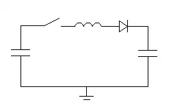
It turns out that with a perfect diode and no losses you can successfully take all the energy from the left cap and put it in the right cap. 15mJ is successfully transferred from a 3uF cap to another 3uF cap and the voltages stabilize out. The diode losses will lose about 2mJ if these are taken into account.
More to follow.
Andy aka
- 434,556
- 28
- 351
- 777
-
I see what you've done here. Without the diode and with the initial condition that one capacitor is charged and the other discharged, the circuit would oscillate (assuming negligible loss to radiation); the capacitors would alternately fully charge and discharge. With the (ideal) diode in circuit, the oscillation goes through 1/2 a cycle and then stops at the point the current goes through zero. Nice. – Alfred Centauri Jul 11 '13 at 14:34
0
probably I'm not skillful enough to say something interesting (I'm not an electronic engineer, only an electronic enthusiast) but I had to overcome the energy transfer problem through capacitors in the past and I've "partially" found a solution (tested inside my little lab).
The idea is similar to the one schematized by Andy Aka but, instead of a simple inductor, I used a complementary one and, instead of a simple diode, I used a Schottky one (to exploit the avalanche effect): I discovered that with these two components put in series I was able to transfer the 65-70% of the energy from the charged capacitor to the empty one.
I think that the amount/percentage of the transferred energy could depend on the resonance frequency: I had no time nor resources to test all the possible harmonics of that resonance, so further investigation is needed.
If anyone found appreciable solutions about this problem, please come in contact with me: fabrizioricciarelli@gmail.com
Cheers
Devesh
Devesh
- 55
- 6
-
Connecting two differently-charged capacitors via non-inductive wire is analogous to an inelastic collision between two objects; conservation of momentum will imply loss of kinetic energy. Adding an inductor would be equivalent to adding elasticity; just as adding elasticity would make possible a variety of combinations of ending velocities where kinetic energy and momentum are both conserved, so too would adding inductance make possible the conservation of electrical energy. – supercat Mar 25 '14 at 16:54