1

I'd say that the cutoff frequency of the circuit in the following scheme is given by \$f_0=\frac{1}{2 \pi (R_1//R)C}\$ but I don't know how to prove this idea. Do you agree with me? What would you say?

schematic

simulate this circuit – Schematic created using CircuitLab

JYelton
  • 32,302
  • 33
  • 134
  • 249
sunrise
  • 287
  • 3
  • 10
  • 3
    What's that funny, upside-down voltage source going to nowhere? What node is the input? What node is the output? With no signal, in or out, it's rather hard to say what this circuit does to said nonexistant signal. – Phil Frost Jul 09 '13 at 23:44
  • Terminology: "corner frequency", "-3db frequency" or "critical frequency" are better terms than "cutoff". Cutoff implies no signal. Like when a bipolar transistor is cut off, there is next to no collector-emitter current. – Kaz Jul 10 '13 at 00:40
  • 2
    This question is not complete. Where is the input and where is the output? It is meaningless to think about the transfer function, if you don't indicate where the signal is being injected and where it is being drawn from. Is the location of the disconnected DC voltage source the signal injection point? Where is the signal pickup point? If I were to guess, it would be at the top of the grounded resistor, which is intended to be the load. – Kaz Jul 10 '13 at 00:55
  • Is R1 intended to be the 10R resistor? Is its value 10 times R or arbitrary? – Austin Nov 20 '15 at 21:01

4 Answers4

5

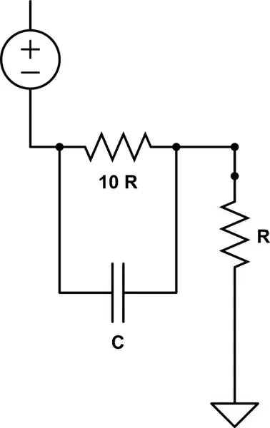
Ignoring the oddly drawn voltage source and looking just at the passive network with the output at the "top" of the resistor R, what you have here is a high pass shelving filter.

At zero frequency, the capacitor is an open circuit and the circuit is just a resistive voltage divider with a gain of \$\frac{1}{11} \$.

At "infinite" frequency, the capacitor is a short circuit and the output equals the input (the gain is 1).

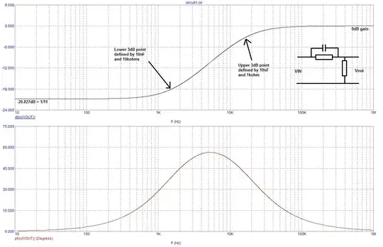
So, this filter has a lower frequency zero (where the gain starts increasing) and a higher frequency pole (where the gain levels off). In the phasor domain, the transfer function is:

\$\dfrac{V_{out}}{V_{in}} = \dfrac{1}{11}\dfrac{1 + j\omega 10RC}{1 + j \omega \frac{10}{11}RC} \$

So, the zero is at \$f_z = \dfrac{1}{2 \pi 10RC}\$ and the pole is at \$f_p = \dfrac{11}{2\pi 10RC} \$

Excuse me, can you tell me why fp and fz are evident by inspection?

Let's write the transfer function in the complex frequency domain (the s or Laplace domain):

\$\dfrac{V_{out}}{V_{in}} = \dfrac{1}{11}\dfrac{1 + s10RC}{1 + s\frac{10}{11}RC} \$

Now, this transfer function has a zero where the numerator equals zero. To find where this occurs, solve for the value of s where the denominator equals zero.

\$1 + s10RC = 0 \rightarrow s_z = \dfrac{-1}{10RC} \$

So this transfer function has one left hand plane (LHP) zero.

The transfer function has a pole where the denominator equals zero (the transfer function is "infinite" there).

\$1 + s\frac{10}{11}RC = 0 \rightarrow s_p = \dfrac{-11}{10RC}\$

So this transfer function has one LHP pole.

This is where the terminology zero and pole come from. So, how can I get from "inspection" the pole and zero frequency from the original transfer function?

The zero (pole) frequency is where the real and imaginary parts of the numerator (denominator) are equal. Since the real part is 1, we can see, by inspection, the frequency where the imaginary part is 1.

For higher order filters, one must express the numerator and denominator as products of terms like \$(1 + j\dfrac{\omega}{\omega_1})\$ in order to read off the zero and pole frequencies like I've done here.

Alfred Centauri
  • 26,502
  • 1
  • 25
  • 63
  • Wonderful answer! Did you obtain \$f_p\$ finding the \$\frac{V_{out}}{V_{in}}\$ magnitude and putting it equal to 0.7, aren't you? How have you obtained \$f_z\$? Many thanks again! – sunrise Jul 10 '13 at 07:56
  • 1
    @sunrise, by writing the transfer function in standard form as I did, \$f_p\$ and \$f_z\$ are evident by inspection. Note that the frequency where the gain is -3dB (or 0.707) is not necessarily \$f_p\$ as another answer here shows. This is due to the fact that the zero and pole frequency "close enough" in frequency to interact. – Alfred Centauri Jul 10 '13 at 11:31
  • Excuse me, can you tell me why \$f_p\$ and \$f_z\$ are evident by inspection? – sunrise Jul 10 '13 at 12:49
  • 1
    @sunrise, I've updated my answer to address your comment. – Alfred Centauri Jul 10 '13 at 13:14
  • Thanks a lot for your answer very clear and detailed! I didn't know the frequency domain before.. It's very interesting! Thanks again – sunrise Jul 10 '13 at 13:51
  • I have only two last doubts: if I use the formula that I have written in the question, I obtain the same result that I obtain if I use your formula for fp. How is it possible? And, if fp isn't the corner frequency, why (seeing at the oscilloscope) do I obtain V_ou/V-in=0,7? – sunrise Jul 10 '13 at 14:13
  • @sunrise, your formula is correct for the pole frequency. If you do the calculation, you'll find that the gain at the pole frequency is 0.710 so the pole frequency is just *slightly* higher than the "corner frequency" where the gain is 0.707. The answer by Kaz has an error that I'll point out shortly. – Alfred Centauri Jul 10 '13 at 14:31
  • @AlfredCentauri,great answer. However, my intuition says that the (almost) perfect match between pole's frequency and -3bB frequency is just a coincidence (due to specific choice of components). This may be checked by writing the equations explicitly, but I feel that you might know the answer already. What do you think? – Vasiliy Jul 11 '13 at 07:24
  • @VasiliyZukanov, it's the fact that the zero and pole frequencies are spaced slightly over a decade apart. If we removed the zero, the pole and -3dB frequency would be identical. If the zero were closer in frequency to the pole, the -3dB frequency would be quite a bit lower than the pole frequency. For example, if it were 2R rather than 10R, the gain at the pole frequency would be -2.56dB. – Alfred Centauri Jul 11 '13 at 10:55
  • @AlfredCentauri, so the rule of thumb in cases like this (single pole and zero) would be that the closer the zero to the pole, the more pole's frequency deviates from -3dB. Is this statement makes sense? – Vasiliy Jul 11 '13 at 11:18
3

This innocently looking bastard is in fact a great question for an interview.

Let's try an intuitive approach first:

We know that a parallel RC is a low-pass filter. If R2 (the grounded resistor) is removed - you'll get the usual RC high-pass curve (for a current). It means that if you ground the other end of parallel RC circuit, then you'll get the maximal current at high frequencies.

Now you might think the following: "Ok, so the parallel RC is a simple high-pass for current, therefore if I put a resistor there (R2), I'll get a simple high pass for the voltage too.". The problem is that the voltage developed across R2 interfere now with the voltage across the parallel RC - the more voltage falls on R2, the less voltage is on parallel RC (kind of negative feedback). This interaction is what makes your prediction for a cutoff frequency incorrect.

Now it is time for equations:

In order to know the current response we need to calculate the complex impedance of the whole network, and derive its real part for magnitude. Equating the square of magnitude to 0.5, one can find a cutoff frequency: Impedance calculation

I tried to use Wolfram in order to derive a solution for \$\omega\$ in a general case, but it failed. Then I tried to reduce the number of symbols by assuming R1=10R2, and it succeeded. However, the answer I got looks suspiciously unphysical (unless someone could explain to me the meaning of complex frequency). Can someone find the mistake?

NOTE1: even if this approach will work, and you'll find a 3dB frequency, it is a question what kind of filer is this. At high frequencies the capacitor behaves as a short, therefore the output voltage will be equal to input voltage. Conclusion: it is oddly behaving high-pass filter.

NOTE2: high pass behavior may be also derived from a general equation for impedance's magnitude - substitute infinity for \$\omega\$ and you'll get R2 as impedance.

Vasiliy
  • 7,323
  • 2
  • 21
  • 38
  • I also tried solving a [similar equation](http://www.wolframalpha.com/input/?i=solve+abs%28%280.01+*+i+*+w+%2B+1000%29+%2F+%280.01+*+i+*+w+%2B11000%29%29+%3D+1%2Fsqrt%282%29++for+w) with WA and got a complex frequency. The real part corresponded to the actual solution as seen on the graph. I'm still not sure what's going on with the math. – Fizz Nov 11 '15 at 23:16
  • The problem is http://electronics.stackexchange.com/questions/200175/finding-the-cut-off-frequency The thing is that even for a RL filter WA gives a complex frequency result when solved [that way](http://www.wolframalpha.com/input/?i=solve+abs%28%280.01+*+i+*+w%29+%2F+%280.01+*+i+*+w+%2B10000%29%29+%3D+1%2Fsqrt%282%29++for+w). So I'm probably missing something basic. – Fizz Nov 11 '15 at 23:31
  • One of the issues is that WA assumes all those parameters to be complex numbers. Unlike Mathematica, you [cannot really tell it to assume some parameter is a positive real!](http://math.stackexchange.com/questions/1525058/wolfram-alpha-simplify-or-assuming-syntax) – Fizz Nov 12 '15 at 06:24
  • I have solved the other problem, if you're curious... by making some hand steps since WA was botching those. – Fizz Nov 20 '15 at 11:51
2

I think you misunderstand what this circuit does. It doesn't have a simple cut-off frequency because there are two points in the spectrum where there are important changes in the gain characteristic.

At DC the gain is 1/11 and this will remain largely so until the impedance of C starts to reduce to match (due to rising frequency) the magnitude of the resistance 10R. This is where the first "3dB" point will be and the gain for higher frequencies will be starting to rise.

It will continue rising until it starts to level out and the recognized "3dB" point for this is when the impedance of C has fallen to match R. From here, as frequency rises the gain starts to become unity.

Thus there are two formula for the two separate points in the spectrum; one dependent on 10R and one dependent on R. Those points are described by the formula in your equation but there will two equations; one containing R and one containing 10R. If the resistor values are closer together in value (than the 10:1 ratio in your question) the two points in the curve will start to merge and I would not hesitate to solve this the lazy way with a circuit simulator: -

enter image description here

Andy aka
  • 434,556
  • 28
  • 351
  • 777
  • Hi, Andy. No, I haven't misunderstood how the circuit works. I have supposed that, using the formula that I wrote in the question, I'd have obtained the "-3db frequency". Then, looking at the oscilloscope, at that frequency, I obtained \$\frac{V_{out}}{V_{in}}\$=0.7 and so this fact seemed confirm my supposition. There is another fact: if you use the formula that I wrote in the question and the formula that Alfred Centauri wrote for fp, you obtain the same result... so I suppose that the circuit "sees" the two resistor as in a sort of parallel.. – sunrise Jul 10 '13 at 14:01
0

To actually calculate the -3dB cutoff/rolloff/corner frequency, it's not enough to compute the poles and zeros as in the accepted answer. You have to do what Vasiliy started to do, but didn't quite finish. I have done that for a similar question. First the transfer function for

enter image description here

(ignore the numerical values in there) is a voltage divider \$R_1||\frac{1}{sC}\$ with the drop over \$R_2\$ as the measurement so

$$H(s) = \frac{R_2}{R_2+\frac{1}{\frac{1}{R_1}+sC}} = \frac{R_2+CR_1R_2s}{R_1+R_2+CR_1R_2s}$$

If you actually make these \$R_2 = R\$ and \$R_1 = 10R\$ you'll get the same transfer function as in Alfred's answer. However, to actually calculate the -3dB rolloff/corner/cutoff frequency precisely, you need to first calculate the square of the gain as product of the transfer function with its [complex] conjugate, which here gives:

$$(G(j\omega))^2 = H(j\omega)\overline{H(j\omega)} = \frac{R_2+j\omega CR_1R_2}{R_1+R_2+j\omega CR_1R_2} \frac{R_2-j\omega CR_1R_2}{R_1+R_2-j\omega CR_1R_2} = \\ = \frac{R_2^2 + (CR_1R_2\omega)^2}{(R_1+R_2)^2+(CR_1R_2\omega)^2}$$

Now equating this squared gain with 1/2 and solving for omega yields:

$$\omega = \frac{\sqrt{R_1^2+2 R_2 R_1-R_2^2}}{C R_1 R_2} = \frac{1}{C R_2}\sqrt{2-\Big(\frac{R_2}{R_1}-1\Big)^2}$$

Note that this expression is fairly similar to the solution to the high-pass filter with a non-ideal inductor. Furthermore if \$R_1\$ is infinite (i.e doesn't exist) then you get the classic result for a RC high-pass filter. And finally as @Andy aka somewhat correctly notes, a notion of rolloff frequency isn't always well defined for this circuit/formula; more precisely the notion only makes sense (and the above solution is real) when \$R_2 < (1+\sqrt{2})R_1 \$; this condition is actually met in circuit from the problem statement, however if you [say] decrease \$R_1\$ too much, then there isn't any point where the gain drops to -3dB. Here's confirmation in simulation of what happens at the boundary \$R_2 = (1 + \sqrt{2}) R_1 \approx 2.42 R_1 \$):

enter image description here

Finally note that in the -3dB rolloff frequency formula, the resistors aren't actually in parallel in terms of the formula they appear in. Since I see the simple Bode plot (poles and zeros) method keeps getting upvotes, it's worth comparing the two predictions.

By approximating the rolloff frequency with the pole frequency (which you have to remember is only an approximation in general), the prediction is that the -3dB frequency is simply at the pole, which (ignoring the LHP sign) is:

$$ \omega_p = \frac{1}{C( R_1||R_2)} = \frac{1}{CR_2}\frac{R_1+R_2}{R_1} = \frac{1}{CR_2}\Big({1+\frac{R_2}{R_1}}\Big)$$

(If you substitute the values for the resistors you get the same formula for this as Alfred.)

If you denote \$ R_2/R_1\$ as \$x\$, you'll see that the pole approximation for the -3dB frequency is only good in the neighborhood of \$x = 0\$ (i.e. when \$R_1\$ tends to infinity). For this problem, you are essentially approximating \$\sqrt{2-(x-1)^2}\$ with \$1+x\$ when you use the pole frequency as the -3dB rolloff frequency.

enter image description here

Fizz
  • 14,355
  • 2
  • 43
  • 97