1

How to chain one transistor's output with another circuit (multi-vibrator for example, but may be some other sound generating circuit on discrete transistors)?

The R1-Q1 with addition of a 1k resistor and LED works fine from collector: LED is ON when I connect R1 and OFF, when I disconnect it.

Now, I want to produce some sound with a multivibrator, when R1 resistance drops to 1-2m. The latter just does not work from collector!

(Of course, multivibrator works fine when Q2 and Q3 emitters are connected directly to ground).

Maybe, there is a better way to control circuits like multivibrator from collector?

enter image description here

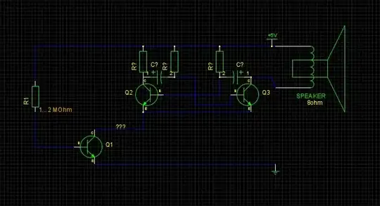
UPDATE: R1 is MegaOhm, sorry for typo.

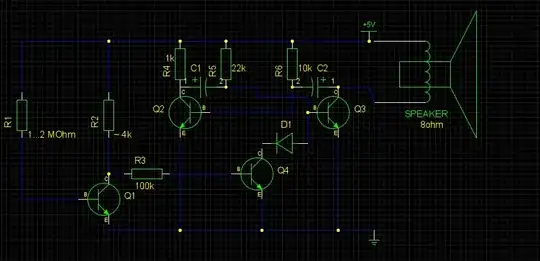
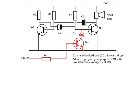
UPDATE 2: Thanks to hints from JIm Dearden, the circuit following started to (somehow) work:

enter image description here

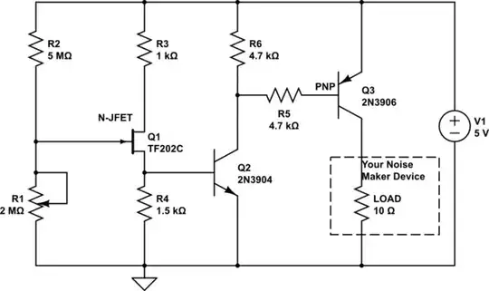
However, I am going to implement better (and more general solution): Schematics for device, which reacts to water?

Disclaimer: any mistakes in the circuit are solely mine.

Roman Susi
  • 985
  • 3
  • 13
  • 30

3 Answers3

1

If you want to use BJT's to implement a reliable switch which activates when a resistance drops to 1M, then put the 1M across the base-emitter junction. Use a pair of transistors to invert the switching signal.

Something like this architecture:

schematic

simulate this circuit – Schematic created using CircuitLab

Why we use a JFET is because the resistance we are sensing is very high, so it helps us to have a device that has a very high input impedance.

The values are very fiddly. With a 5V supply, you need a JFET that pinches off easily: a JFET is pinched off when the gate voltage is below the source voltage, which is why we need R4.

The extra Q2 stage is used to create voltage gain so that there is a sharper turn-on.

Here is the simulation (DC Sweep) which shows the load current, as the potentiometer is varied from 0 to 100%. It is fairly sudden around the middle position. But this depends on the JFET characteristics. Experimentation with R2, R4 and R3 is necessary with different JFETs.

enter image description here

Kaz
  • 19,838
  • 1
  • 39
  • 82
1

I find the question very confusing but if you want to turn the multivibrator on and off with another transistor (Q1). All you need to do is pull the base of one of transistors (Q2 or Q3) down to ground - preferably Q3 as it has the largest load and so switching Q3 off would save current consumption.

To turn the transistor (Q3) OFF its base-emitter voltage needs to be pulled below 0.6V.

Q1 will be subject to a negative voltage on its collector due to the switching action on the capacitor C1 which could cause it to breakdown. A Schottky diode (low forward voltage drop) is used to protect the transistor Q1 but still allow it to pull the base voltage below 0.6V.

As you don't give values its difficult to calculate the size of R4 but 1M0 would give a base current of 4.4uA and a collector current (assuming gain = 250) of about 1mA. If R3 is greater than 5k (5V/1mA) this should put Q1 into saturation.

enter image description here

JIm Dearden
  • 18,926
  • 30
  • 40
  • Thanks for your input. Sorry if the question seems to be confusing. Maybe I can be better off finding some ready schematics (as what I am trying to build is surely very primitive), but I want to learn in the process. – Roman Susi Jul 09 '13 at 20:39
  • Is C1815GR good for low saturation Q1? VCE(sat) typ. = 0.1v, Hfe=200-400? – Roman Susi Jul 10 '13 at 19:27
  • Hmmm... I have R3=22k, and when I try 670Ω (instead of CE of Q1) with diode (not Schottky), Q3 is barely closed. 1kΩ resistor almost closes Q3, as I can hear some high frequency noise. (Tester shows Hfe=290 for C1815GR) – Roman Susi Jul 10 '13 at 20:01
  • The prev. comment assumed 3.3v power. – Roman Susi Jul 10 '13 at 20:11
0

With \$R1=1M\Omega\$, the base current will be about:

$$ \frac{5V-0.6V}{1M\Omega} \approx 4.3\mu A $$

The current gain (\$\beta\$) of the transistor might be as low as 30, and probably not more than 150 (and gets worse with increasing frequency; check the datasheet). Even with an optimistic guess of 150, the collector current will be limited to:

$$ 4.3\mu A \cdot \beta = 640\mu A$$

You don't specify the other resistor values, but it's a reasonable guess that the current passing through the multivibrator is more than this. Thus, Q1 never reaches saturation, and doesn't look like a closed switch, and instead significantly impedes the current that the multivibrator needs to function.

As a solution, use a smaller R1, or use a MOSFET for Q1. As a rule of thumb, the base current should be about 1/15th of the maximum collector current you anticipate, if your intention is to drive the transistor into saturation to use it as a switch.

Phil Frost
  • 56,804
  • 17
  • 141
  • 262
  • Agh... Sorry I've made a typo: its megaohm! – Roman Susi Jul 09 '13 at 19:31
  • Alternative for mosfet: darlington transistor, if none is available a DIY darlington can be used. – Wouter van Ooijen Jul 09 '13 at 20:06
  • @Phil Frost: Can't change R1, as the whole point is to "sense" it's resistance. – Roman Susi Jul 09 '13 at 20:12
  • @RomanSusi that's not really the problem you specified in your question. I've addressed your problem, and you have [a new problem](http://electronics.stackexchange.com/questions/ask), along the lines of "How can I switch a transistor when a resistance reaches a threshold?" – Phil Frost Jul 09 '13 at 20:48
  • Nope. The circuit should make sound when resistance drops from practical infinity to 1-2 megaoms. (its illustrated in the original question by LED ON/OFF example). – Roman Susi Jul 09 '13 at 21:02
  • @RomanSusi I haven't read all your questions, and your schematic has a fixed resistor in it. And, sensing resistance is not the problem posed by your title. Besides the one word "drops", there is nothing in your question about your actual problem. Fortunately, Kaz has given you a solution, but if you try harder to ask clear, focused questions, you will get better answers, and people will be less annoyed when they take the time to answer your question (twice!) only to have you tell them that they weren't able to divine the question you were *actually* asking. – Phil Frost Jul 09 '13 at 21:28
  • I will try to be more precise with schematics. In this case I just did not know what symbol to use for "R1" (just a pair of electrodes, like in http://electronics.stackexchange.com/questions/28483/what-are-viable-approaches-to-a-circuit-to-detect-wet-moist-cloth-bed-wetting ?), which is actually a kind of sensor. – Roman Susi Jul 10 '13 at 04:02