24

Consider this simple sketch of a circuit, a current source:

circuit

I'm not sure how to calculate the power dissipation across the transistor.

I'm taking a class in electronics and have the following equation in my notes (not sure if it helps):

$$P = P_{CE} + P_{BE} + P_{base-resistor}$$

So the power dissipation is the power dissipation across the collector and emitter, the power dissipation across the base and emitter and a mystery factor \$P_{base-resistor}\$. Note that the β of the transistor in this example was set to 50.

I'm quite confused overall and the many questions here on transistors have been very helpful.

David Chouinard
  • 479
  • 1
  • 6
  • 13

4 Answers4

32

Power isn't "across" something. Power is the voltage across something times the current going through it. Since the small amount of current going into the base is irrelevant in power dissipation, calculate the C-E voltage and the collector current. The power dissipated by the transistor will be the product of those two.

Let's take a quick stab at this making some simplifying assumptions. We'll say the gain is infinite and the B-E drop is 700 mV. The R1-R2 divider sets the base at 1.6 V, which means the emitter is at 900 mV. R4 therefore sets the E and C current to 900 µA. The worst case power dissipation in Q1 is when R3 is 0 so that the collector is at 20 V. With 19.1 V accross the transistor and 900 µA through it, it is dissipating 17 mW. That's not enough to notice the extra warmth when putting your finger on it, even with a small case like SOT-23.

Olin Lathrop
  • 310,974
  • 36
  • 428
  • 915
  • Thank you, Olin. Very appreciated, it's much clearer now. – David Chouinard Jul 07 '13 at 17:38
  • This "principle" is also scalable to the big IGBT drivers for power electronics but you do need to read the component datasheets where effective resistance at particular currents needs to be considered. Also applies to Diodes, SCRs and Inductors as well. In fact anything that creates a voltage drop and or resistance. – Spoon Jul 07 '13 at 22:29
  • "Power is the voltage across something times the current going through it" One must take care that this is total electric power, but not necessarily *dissipated* power, only the component of current that is in phase with voltage contributes to the increase of entropy in the system – lurscher Apr 20 '19 at 14:37
  • Cool thanks! B-E drop is 700 mV thats because it's like any diode has a drop near like that, though why is it 19.1 V across the transistor? Is it some kind of another diode drop or does it have something to do about R4 resistor? – igrek Jul 20 '20 at 21:20
  • Ohh, so it's 900 µA times 1kΩ == 0.9V – igrek Jul 20 '20 at 21:46
13

Power is the rate at which energy is being converted into some other energy. Electrical power is the product of voltage and current:

$$ P = VI $$

Usually we are converting electrical energy into heat, and we care about power because we don't want to melt our components.

It doesn't matter if you want to calculate the power in a resistor, transistor, circuit, or waffle, power is still the product of voltage and current.

Since a BJT is a three-terminal device, each of which may have a different current and voltage, for the purposes of power calculation it helps to consider the transistor as two parts. Some current enters the base, and leaves the emitter, through some voltage \$V_{BE}\$. Some other current enters the collector and leaves the emitter through some voltage \$V_{CE}\$. The total power in the transistor is the sum of these two:

$$ P = V_{BE}I_B + V_{CE}I_C $$

Since the goal of using a transistor is usually to amplify, the collector current will be much larger than the base current, and the base current will be small, small enough to be neglected. So, \$I_B \ll I_C\$ and the power in the transistor can be simplified to:

$$ P \approx V_{CE} I_{C} $$

Phil Frost
  • 56,804
  • 17
  • 141
  • 262
  • Thanks, Phil, that's helpful. That assumption goes a long way in simplifying calculations. – David Chouinard Jul 07 '13 at 17:26
  • Also, the β of the transistor is 50. Since that value is small, not sure if that causes the other factors significant enough to be important. – David Chouinard Jul 07 '13 at 17:30
  • 2
    @DavidChouinard The relative significance of the powers also depends on the ratio of \$V_{BE}\$ to \$V_{CE}\$, but if \$I_C\$ is 50 times larger than \$I_B\$, it will be hard for the power due to base current to be significant. I added the unsimplified calculation so you can see how it's relevant. – Phil Frost Jul 07 '13 at 17:38
  • if one would just use \$V \times I\$ on a capacitor or inductor, one would obtain accumulated power BUT not the dissipated power, as those components (in their pure form) do not increase the entropy of the system. I am not convinced of this argument – lurscher Apr 20 '19 at 14:32
  • @lurscher You're right an ideal capacitor doesn't get hot, but that doesn't mean P=VI is false. Power is the rate of doing work: there's no requirement that the work goes into making heat (although that is a very common case, and one that applies in the case of transistors, the subject of the question) – Phil Frost Apr 20 '19 at 18:09
  • @PhilFrost right, P = VI represents total power: \$V I_{\parallel}\$ is the power associated with entropy increase (with \$I_{\parallel}\$ means the phasor component of current parallel to voltage), while \$V I_{\bot}\$ is the stored power that is thermodynamically recoverable (with \$I_{\bot}\$ means the phasor component of current orthogonal to voltage) – lurscher Apr 21 '19 at 01:18
  • 1
    @lurscher Neat. So what exactly is your issue? – Phil Frost Apr 21 '19 at 02:22
  • I have no issue beyond clarifying that \$V I\$ does NOT stand for dissipated power in the general case – lurscher Apr 21 '19 at 02:44
  • @lurscher Though the product \$p(t)=v(t)i(t)\$ _always_ represents the instantaneous power _"consumed"_ by a lumped two-terminal network, provided the reference polarity and direction for the instantaneous voltage and conventional current are defined such that the passive sign convention is satisfied. Positive values indicate power is indeed “consumed”, so net electromagnetic energy flows into the network (the network is acting as an energy sink/load), negative values indicate power is actually “generated”, so net EM energy flows out of the network (the network is acting as an energy source). – alejnavab Mar 15 '22 at 06:12
2

In the special case of your circuit, because there exists just one transistor, you can find it's power dissipation using conservation of power in your circuit: $$P_{source}=P_{R1}+P_{R2}+P_{R3}+P_{R4}+P_{BJT}$$ $$I_{R1}=I_{R2}=\frac{V_1}{R_1+R_2}=0.16mA$$

Now we find the current of R1 and R2. The current of the base is neglected:

$$V_{R4}+V_{BE}=V_{R2}\to I_{R3}=I_{R4}=0.9mA$$

So the total power dissipated in resistors will be : $$\sum_{R_1}^{R_4}R_iI_i^2=12.11mW$$

The power that source gives to the circuit is:

$$P_{source}=I_{source}V_{source}=21.2mW$$

Now we find the power dissipation in transistor using the first relation above:

$$P_{BJT}=9.09mW$$

Zorich
  • 139
  • 5
1

Here is an answer which is more rough, but easy to recall and useful as a first approximation. Only the case of a NPN bipolar junction transistor is dealt here; things are similar for PNP bipolar junction transistors.

The basic assumption is that the B-E current is negligible with respect to the current through the collector, so, the collector current is approximately equal to the base current: $$I_E = I_C = I.$$ If this assumption does not hold, then the transistor is probably misused or subject to a catastrophic failure.

Now, the power dissipated by the transistor is of course $$P = V_{CE} I.$$ 
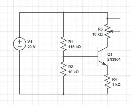
To obtain an upper bound that is useful in the general case, we model the problem by considering that the collector is connected to \$V_{CC}\$ through a resistor \$R_3\$, and that the base is connected to the ground through a resistor \$R_4\$ (this includes the load etc.). This is exactly the case in the OP problem. We have:

$$V_{CE} = V_{CC} - R_3 I - R_4 I = V_{CC} - (R_3+R_4)I,$$ hence $$P = (V_{CC} - (R_3 + R_4)I) I.$$ Using infinitesimal calculus, you find this expression of P is maximal whenever $$I = V_{CC}/2(R_3+R_4),$$ and equal to $$P^* = V_{CC}^2/4(R_3+R_4).$$ This is the desired upper bound for the dissipated power whenever \$R_3\$ and \$R_4\$ are known. It means that:

Theorem: the power dissipated by the transistor is not larger than \${1\over 4}\$ of the power that would be dissipated by the two resistors \$R_3\$ and \$R_4\$ if they were directly connected.

In the OP problem, \$R_3\$ is furthermore allowed to vary between 0 and 10kOhm, so, it is obvious that the expression of \$P^*\$ will be maximal for \$R_3=0\$. This gives the upper bound $$P^{**} = V_{CC}^2/4R_4 = 100mW,$$ larger than, but not so far from, Olin Lathrop's bound.

MikeTeX
  • 1,834
  • 1
  • 13
  • 32