0

I am using a variation on the following Arduino project and it works, though I'm not quite sure how when it comes to the push button:

http://ardx.org/BBLS07/

The schematic (from p22 of http://oomlout.com/products/ARDX/ARDX-experimenters-guide-DD.pdf‎):

enter image description here

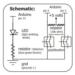
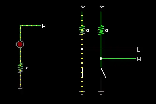
The 5V voltage source runs through a 10K resistor, which is connected to pin 2 and the push button.

I believe that the circuit works like so: when the button is not pushed, it is a series circuit, and current only flows through the wire leading to pin 2. (Notably, the default state for digital pin 2 in the Arduino sketch is HIGH, not LOW.) When the button is depressed however, the circuit becomes parallel. Somehow, the circuit's action is constituted by this. Even if I'm essentially right I'm missing some details, so fill me in here.

Wouter van Ooijen
  • 48,407
  • 1
  • 63
  • 136

2 Answers2

2

The circuit is drawn badly, but still understandable. Without a button pressed, pin2 is pulled high (+5V) by the left 10k resistor. When the left button is pressed, pin2 is connected to ground via the very low resistance of the switch, so the voltage on it will be near 0V.

The right 10k resistor and switch work the same way.

Wouter van Ooijen
  • 48,407
  • 1
  • 63
  • 136
  • I agree, it took me a couple extra seconds to understand the operation of the switches. – Nick Williams Jul 06 '13 at 13:33
  • That's a start but I'm still kind of confused about how pull-up resistors work, despite having looked at a few online resources. – readyready15728 Jul 06 '13 at 15:26
  • The circuit is drawn in a non standard way to make it easier to build I assume. Think of pull ups as feeding a voltage to your pin, but only a small current is allowed, then when you want a low on the pin you over ride it by connecting it to 0V. The resistor is only allowing a small current to flow. If a large current flowed it cause problems. – Spoon Jul 06 '13 at 16:12
  • Agreed - horribly drawn circuit, but very common with Arduino circuits. Without trying to add even further confusion, the pullup resistors are completely unnecessary in this case as the Arduino has internal pullups which can be activated in software. – Kurt E. Clothier Jul 06 '13 at 19:03
1

There are basically three circuits here, if you ignore the horrible drawing quality:
enter image description here
(click for simulation)

Connor Wolf
  • 31,938
  • 6
  • 77
  • 137