7

I would like to mount a slow-moving robotic "car" to a linear track of any incline from horizontal to vertical. The track should be rigid (attached to a boom if necessary) so that it can be propped up on one end or leaned against a wall to provide the incline.

The car should be able to:

  • carry an 800 g load when the track is exactly vertical,
  • move approximately 5 cm/min,
  • hold position without power, and
  • travel several meters or more.

I suspect I need hardware such as the following, but I don't know where to begin. Can anyone help narrow my search?

  • Track hardware
  • Drive system for a small platform weighing upwards of a kilogram
  • Brake (to allow the car to remain at rest with zero work)
Isaac Sutherland
  • 771
  • 2
  • 8
  • 17
  • 1
    5 cm/minute = 3 meters an hour; what needs to travel so blindingly slow? I'd almost think it would be better to move a little faster do you don't have to be "on", moving a motor, for so long. – Nick T Dec 05 '10 at 00:09
  • What kind of translation resolution do you need? – tyblu Dec 05 '10 at 00:41
  • 2
    I'm trying to do time-lapse photography with a moving camera. So I need the car to move very slowly, and I need it to be stationary during exposures. – Isaac Sutherland Dec 05 '10 at 08:16
  • I'm not familiar with the terminology, but if "translation resolution" means the degree of accuracy to which I can control the car's position, I'm hoping for error of no more than +/- 2 mm. Does that sound reasonable with hobby components? – Isaac Sutherland Dec 05 '10 at 08:25
  • Quite reasonable. – tyblu Dec 05 '10 at 08:43
  • Is this going to be strictly linear (no curves/bends)? Do you care where the drive mechanism is--on car vs. track? What sort of budget? – Nick T Dec 20 '10 at 19:45

6 Answers6

9

Drive the car with a threaded rod rotated by a stepper motor. A captive nut on the car attaches to the motor.

russ_hensel
  • 2,904
  • 16
  • 12
  • 1
    Probably the best option unless you're going really far (though at 5 cm/min, kinda doubt it) Some sort of split nut would be a good idea so you can attach it wherever without having to thread it the whole way. – Nick T Dec 03 '10 at 22:41
  • 1
    Even with coarse thread and 7/16" threaded rod, you get 1.8mm per rotation, so, if you don't need better resolution than that, a stepper is not required. Just a magnet and hall switch with a regular motor. – tyblu Dec 04 '10 at 03:37
  • Actually, I do intend for the car to move several meters or more over time. I'll edit my question to reflect this. – Isaac Sutherland Dec 04 '10 at 03:42
5

How about a linear Toothed rubber belt running along the track.

I've seen this used in machinery that worked quite well.

A pair of pickup rollers pick the belt up, and a driver pulley apply torque.

lLnear toothed belt is relatively maintenance free, doesn't need lubrication and will drive equally will in either direction. Fancy big belt stock is silicone rubber and Kevlar, never stretches much, and doesn't need lubricants.

800g is a very small belt ( which is cheaper per metre ) The belt is mounted on the track, tooth side towards the track. the belt is held in tension at both ends, and the pickup rollers and drive pulley have a fixed relationship so it can be pretty backlash free.

excuse my ascii art.

#-----------------0     0------------------#
                  |  O  |
                   \___/


--- belt
0  pickup roller
O center of drive pulley.
# belt tensioner ( belt is stretched with a bolt thread )
Tim Williscroft
  • 1,702
  • 11
  • 11
  • Looks like a ServoBelt to me. – Dave Dec 21 '10 at 06:49
  • Hmmm... not *exactly*, I guess. I assume the idlers are somewhere around 10 and 2 o'clock to keep the drive pulley in place. This is a very cool approach since you can let the belt be floppy as it goes over any sort of "hills" or up "cliffs". +1 for this approach. – Dave Dec 21 '10 at 06:51
  • You could get this stuff from McMaster pretty easily, I might suggest XL-series [pullies](http://www.mcmaster.com/#xl-timing-belt-pulleys) (~$8-10) and [belts](http://www.mcmaster.com/#xl-series-timing-belts) (~$2/ft) – Nick T Dec 22 '10 at 21:20
  • I wasn't thinking of anything as elaborate as a ServoBelt. I've always seen them made out of parts and plates. (McMaster I guess in USA) – Tim Williscroft Dec 23 '10 at 05:19
4

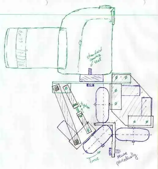
Here's what I would do with my 35-mm camera if I needed it to travel along an accurate trajectory, and consider it to be simple to customize to a specific trajectory and stable enough for a heavy camera. Use a strip of 1/16" to 1/8" thick, 3/4" by 1.5" angle-iron to go from point A to point B, bending to whatever vector you wish at different lengths -- it's possible to bend this by hand (or over your knee). You would need to construct a trolly to grip the track. There are a zillion different ways of doing this; here is one:

Note: this is also a link.
(source: tyblu.ca)

I've put in servo-motors (mounted on gearboxes), but you could use stepper motors. A brake is a chock or wedge shoved under the wheel by a solenoid or spring -- the spring would save you a solenoid, but make the trolley 1-way only. You may not need every wheel to be powered. Also, once one has a trolley they can mount whatever they want however they want on it, so long as it can support the weight and torque. Those Gorilla camera stands look like they could be mounted then positioned arbitrarily. If you really want to get fancy you could give the camera degrees of motion like pan, tilt, and roll.

Path length or position can be tracked in a number of ways; here are some: rotary encoder, using a pre-marked disk attached to one of the shafts, an LED and a photodiode; optical mouse sensor, sensing either wheel rotation or relative angle-iron movement; feedback from servo motors. Note that if resultant travel from incremental motor actuation is well defined, you may be able to deduce total travel and not have to track the path.

I'd fight with myself between this solution and parallel threaded rods. I've used ready-rod before, and it's really easy, but it would be more difficult to secure it, as you could only do it at the ends, whereas this one can be secured along its length.

Glorfindel
  • 1,245
  • 3
  • 15
  • 20
tyblu
  • 8,167
  • 6
  • 40
  • 70
  • +1, probably the most robust option if you've got the parts, and can easily be extended to arbitrary length. – David X Dec 22 '10 at 05:11
  • 1
    +1, Nice solution as your track can be fairly cheap per foot if made out of angle iron or rectangular tube. However, the spacing between the wheels needs to be much wider to reduce the difference in moment arm between your camera and track and wheels and track. The mechanical advantage it gives will drastically amplify any slop in bearings, doubly so because it will also increase the force that you can exert on them. – Nick T Dec 22 '10 at 21:41
  • I'm running with this concept for now as it is the best fit with the hardware I have. Thanks! – Isaac Sutherland Dec 27 '10 at 23:56
  • @Isaac, you may want to sketch several alternatives as well. Time spent on paper saves quite a bit more down the design path. This is only a quick sketch, and, as @NickT commented, it has flaws. – tyblu Dec 28 '10 at 00:30
  • Specifically, at a minimum the camera needs to be moved back so that the overall center of gravity is directly above the vertical wheel. And, as @NickT points out, increasing the moment arm of the driver wheels is a really good idea. – WhatRoughBeast Mar 29 '19 at 14:30
2

If you are going very far, adding a winch to your car may be the best as you can extend it without much trouble. A simple spool driven by a worm gear would prevent movement when unpowered. If you want the powered portion to be fixed, just attach the winch to the top of the elevator (or via pulley to wherever else) and tie it to the car.

As far as a track is concerned, I'd use a couple small wheels (if you don't want to do much fabrication yourself, Lego might be an option) and have them hold a rail (circular or square rod) captive.

Speaking of toys, I'm not sure what's in a K'nex roller coaster, but it might be useful if you can get a cheap/used one.

Nick T
  • 12,360
  • 2
  • 44
  • 71
  • Can you clarify what you mean by holding a rail captive? I'm having a hard time picturing a lego construction that could follow a rail and provide support for a kilogram of load. – Isaac Sutherland Dec 20 '10 at 19:22
  • @Isaac: My link was just for wheels, not really Legos. – Nick T Dec 20 '10 at 19:31
  • @Isaac: I think what Nick is referring to is having wheels above and below the rail. Basically like a roller coaster. – Dave Dec 21 '10 at 06:46
1

Some printers have a clear striped ( across the axis ) material that is scanned by photo cells to make a long linear encoder. This does not move. You could use your current drive ( or almost any other ) and use the encoder for feedback to make the motion as precise as the stripes.

russ_hensel
  • 2,904
  • 16
  • 12
-1

In order for you to get the best answers to your question, I think you need to provide more information about the terrain that you want to attach this track to. You say it can go from horizontal to vertical -- how vertical, and how quickly does the grade increase or decrease? What are the limitations involved in laying down the track? Do you have free reign over what hardware you lay on the ground?

Dave
  • 3,800
  • 24
  • 41
  • I'm picturing a linear boom with a track fixed to it. The boom could be propped up with a tripod on one end to determine its incline. The track itself can be perfectly straight, if curves would make things too complicated. – Isaac Sutherland Dec 23 '10 at 04:35