It is difficult to understand what are you asking about without some sort of timing diagram.
However, I'll try to guess what your issue is:
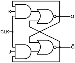
There is broad interchangeable misuse of terms "gated latch", "flip flop" and "edge-triggered flip-flop". The schematic you provided is not JK edge-triggered flip-flop, but JK gated latch, commonly referred as JK flip-flop.
As opposed to edge triggered flip-flops which change state only on the rising edge of the clock signal, gated latches can change state during the whole positive phase of the clock signal. This means that if either J or K inputs change while the clock is high, the output of gated latch may change too (which is not true for edge-triggered flip-flops).
However, if J and K inputs are held constant during a positive phase of the clock, the output of JK gated latch will settle to a known value (with one exception described below), which may be derived from the values of J, K and Q at the rising edge of the clock. NOTE: the fact that we are looking at the values of the signals at the rising edge does not imply that this JK gated-latch is edge triggered, because we assumed that the inputs will not change during positive phase of the clock!!!
Now, to your question: it seems that you can't grasp how exactly the output may settle to a known (and deterministic) value, taking into account the two feedback loops present. Well, the only way you can convince yourself is to assume some initial conditions on the output and trace what happens for each possible combination of inputs (except J=1,K=1).
The following two points will make your life easier:
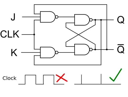
- While the implementation with NAND gates is the most area effective, for the purpose of understanding the concepts it is best to investigate this (functionally equivalent) circuit:
- Note that when the clock is high, the outputs of AND gates will be determined by the values of J and K inputs, and the value of Q. It means that you may erase the clock signal from the diagram in order to understand what's going on during the positive phase of the clock.
EDIT: So what about J=1, K=1 case? Well, in this case JK gated-latch becomes a multivariator (I hope the term is correct) - its outputs will be changing periodically during the positive phase of the clock. In logic circuits this combination of inputs is illegal, therefore the usual practice is to tie them together in the following manner (which is called D gated-latch):
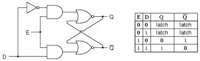
Note that there are no need in feedback in this circuit, because the outputs are completely determined by the value of D input.
In order to construct edge-triggered JK flip-flop, one can put two JK gated-latches in series in the following way (there are also other configurations). Note that the feedback paths are from the output of the second gated latch to the input of first:
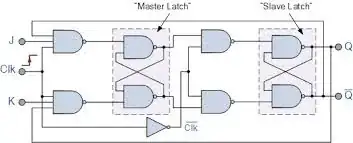
In this configuration there are no more restriction on J=1, K=1 input combination - this combination of inputs means "toggle the output". The so-called T edge-triggered flip-flop is usually derived from the above JK edge-triggered flip-flop by tying J and K inputs together.