Edit: I don't know how I managed to misread 2013 as 2017, but since I found this on google, I'll leave it in the hopes that it'll interest other people
Both of the other answers dealt with your specific situation, however one of the questions you asked is pretty interesting and could have some nice learning opportunities so I'm going to try to deal with it in a more general sense:
couldn't I also use a pulled-down pin as ground
This would work, but it would be entirely dependent on how much current you want the pin to be able to sink. In general, connecting to high resistances such as a microcontroller pin would work, but anything requiring non-negligible current would start to have issues.
Pins with pulldown resistors on them will be slightly above ground - and the higher the value of the resistor the more the pin will be above ground; but for most pulldown values the voltage across them will be negligable. The main issue, however, would be sinking current. What if you wanted to go extreme and ground something beefier than a digital input, like say: a headphone amplifier?
In this case, the chip would need to sink significant currents (100's of milliamps). Lets assume it is connected to an Arduino Uno input pin with a 20kilo-ohm pulldown resistor. The microcontroller in the Uno is an Atmega328, and in the datasheet it lists an input leakage of 1 micro-amp. This is the current that flows through the pulldown resistor to make the pins voltage go low - therefore, when nothing but the pulldown resistor is connected to the pin, the voltage at that pin would equal
$$ V_{pin} = I_{leakage} \times R_{pullup} = 1\mu A \times 20k\Omega = 0.02V $$
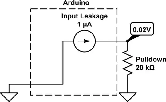
simulate this circuit – Schematic created using CircuitLab
Now, lets connect the headphone amplifier. For simplicities sake we can model the headphone amplifier as a resistor of 50 ohms, this would cause 100mA to flow when connected to 5V.

simulate this circuit
The input resistance of the Uno is about 100 mega-ohm, so it's totally negligible. This means that the resistance of the amplifier would be effectively connected in series with the pulldown resistor. Now, you've got a voltage divider with 50 ohms in the top, and 20, 000 on the bottom! The vast majority of the voltage would be dropped across the bottom resistor, so the chip would see less than 0.01 volts between it's voltage and ground lines, and so it would fail to function.
I'm still learning electronics myself, so don't take this as 100% truth, but I'm pretty sure it's all correct :)
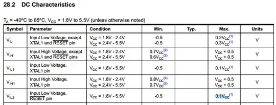 Take a look at the "Input low voltage, RESET pin". It states as max $$ 0,1 * Vcc $$