39

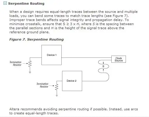
On some PCB designs, specific traces are routed in curious ways. This probably has to do with high frequency design considerations and general signal behavior that I am not familiar with.

Let's take this PCB (somewhere from the web) as an example. It shows part of a PCIe card with SATA routing and DDR2 RAM:

Example PCB

I highlighted 4 areas that qualify as unusual trace layout (from my perspective).

  1. What are those shapes supposed to achieve? How do designers come up with what pattern is required?
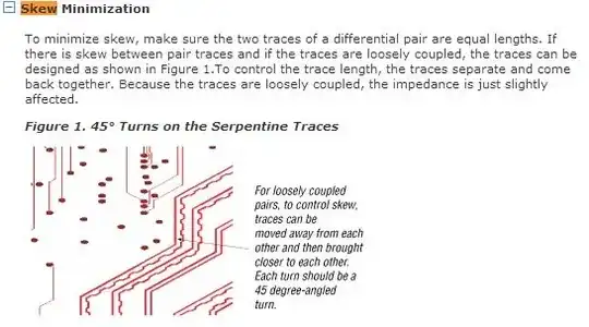
  2. Another example of wave shaped, antenna like routing.
  3. This is fairly rare. But obviously the designer deliberately avoided 45° traces. Why?
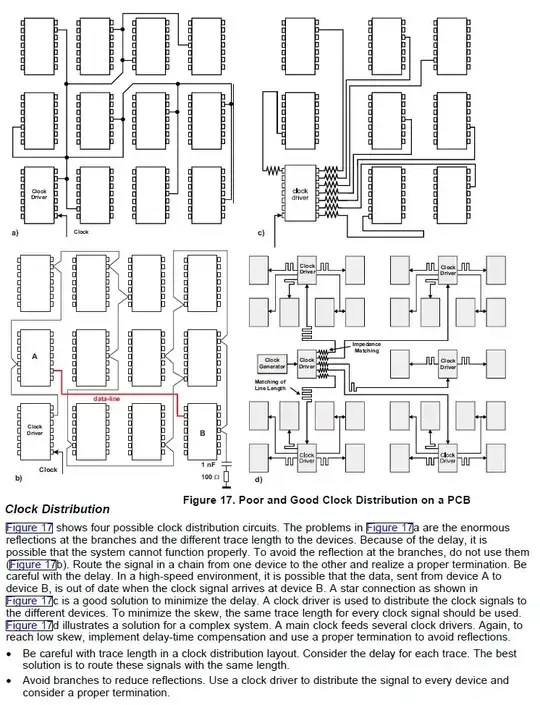
  4. Curves again and a single "pulse" within the trace. How can this have any significant effect?

So what are the use cases and benefits of this techniques?

I want to be able to take those into consideration when doing future PCB designs.

Ricardo
  • 6,134
  • 19
  • 52
  • 85
Rev
  • 10,017
  • 7
  • 40
  • 77
  • 2
    Related question: http://electronics.stackexchange.com/questions/4168/what-is-this-squiggly-trace-for – m.Alin Jul 03 '13 at 07:44
  • 2
    @m.Alin That's only a partial answer to this question. It's on the right track though. Doesn't address the curved traces. – Passerby Jul 03 '13 at 07:49
  • 2
    Guess: 1&4) equalise length of pairs of traces. 2) delay 3) avoid signal reflection at sharp bends. – RedGrittyBrick Jul 03 '13 at 08:12
  • 1
    @m.Alin: Thanks for the link. I didn't search for "squiggly trace" ;) As Passerby noted, this provides a partial answer. But maybe someone can post an answer with respect to the 4 mentioned examples and provide some additional information based on design experience. – Rev Jul 03 '13 at 08:14
  • 3
    @RedGrittyBrick deserves more love for that answer. – John U Jul 03 '13 at 09:11

2 Answers2

37

1) Equalisation of length of pairs of traces

enter image description here
From Board Design Resource Center

2) Delay (e.g. of clock for timing purposes)?

enter image description here

See also Adding delay intentionally

3) Reduce signal reflections due to discontinuities in trace width?

enter image description here
from Circuit Board Layout Techniques

See also How should I lay out timing matched traces?

RedGrittyBrick
  • 14,602
  • 5
  • 37
  • 77
  • Just to note, for 3, I'm assuming that we are not getting the whole picture. That's at least a double sided board. Some of these traces might be routed to avoid routing directly above/below a different set of noisy traces or components. – Passerby Jul 03 '13 at 11:08
  • The Document "Circuit Board Layout Techniques" looks like a nice read. Since it is labeled as "Chapter 17", I wonder what the other chapters are about. Do you have a link to the whole collection? – Rev Jul 03 '13 at 12:41
  • 1
    @Rev: http://www.ti.com/lit/an/slod006b/slod006b.pdf – RedGrittyBrick Jul 03 '13 at 12:43
9

This is not intended to be a complete answer rather it's a useful hint at what designers do when complex clock distribution is required. (courtesy of TI source) showing bad and good clock layout design : -

enter image description here

Andy aka
  • 434,556
  • 28
  • 351
  • 777