7

I'm studying the trasmission of signals though coaxial cable; I'm using a coaxial cable (of course!), an oscilloscope, a generator an some different endings. This is the scheme: enter image description here

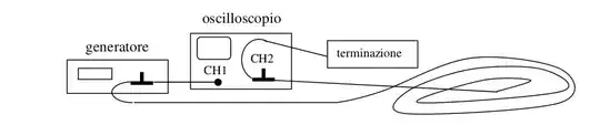
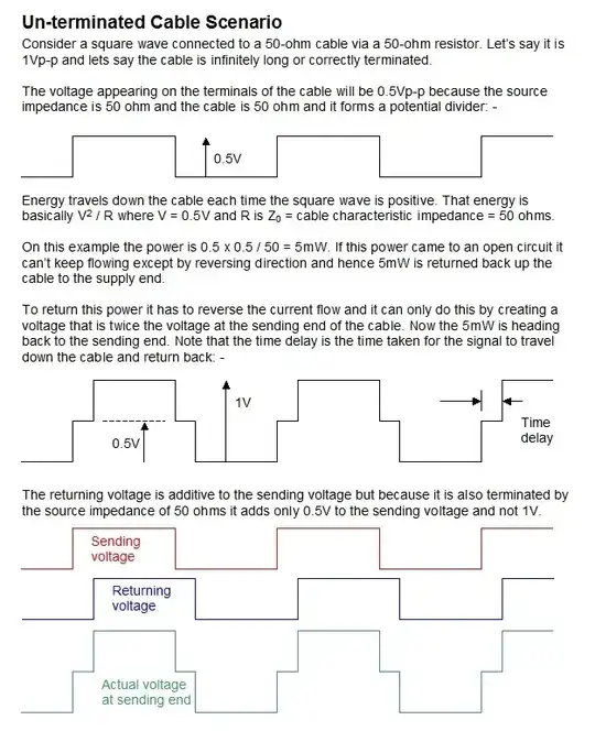
I was told that if I use a very long cable that has impedence \$Z_0= 50 \Omega\$ and put, at the end of it, a resistor of \$47\Omega \$, the signal will be reflected.

I have obtained this:

enter image description here

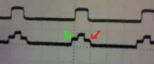
If I have correctly understood, the height of the step pointed by the green arrow is the half of the V given by the generator.

I can't understand why the step pointed by the red arrow is shorter than the one that is on the other side. And I can't understand what's the physical meaning of the step pointed by the red arrow.


Then, I have terminated the cable with a short circuit and I have obtained this: enter image description here

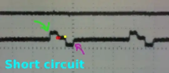
Could you explain me what's up at the points indicated by the two arrows and the yellow and red points?


Then, I have terminated the cable with a resistor of 100 ohm and I have obtained this: enter image description here

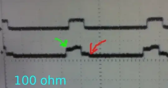
Could you explain me, why the step pointed by the green arrow is higher than the step pointed by the red arrow?

This is the last image: enter image description here

sunrise
  • 287
  • 3
  • 10
  • 2
    I don't think your cable was terminated by 47Ω - if it were 50Ω cable you'd barely see a reflection at all. – Andy aka Jul 02 '13 at 16:22
  • [What's the importance of source impedance termination?](http://electronics.stackexchange.com/questions/73662/whats-the-importance-of-source-impedance-termination) [online transmission line simulator](http://helloworld922.blogspot.com/2013/04/online-transmission-line-simulation.html) – Phil Frost Jul 02 '13 at 17:13
  • @Andyaka I was told that resistor was 47 ohm. Using a termination of 50 ohm, I didn't see any reflection. – sunrise Jul 02 '13 at 17:30
  • This would very nearly be the same with 47R – Andy aka Jul 02 '13 at 17:44
  • @Andyaka Could you explain me why in the short circuit there are three steps? Many thanks!! – sunrise Jul 02 '13 at 19:54
  • Reflections cause these things. You send a pulse down a piece of cable that is 50 ohm cable; when the pulse reaches the cable end and it isn't a 50 ohm resistor then it sends a reflection back up to the source pulse - This reflection adds/subtracts to the source pulse making steps. Sometimes the steps are linear sometimes hard to figure. – Andy aka Jul 02 '13 at 21:00
  • @Andyaka Maybe I'm very near to the comprehension.. :) Does the reflection add to the source pulse when the termination of the cable is a resistor with resistance bigger than 50 ohm and is it subtracted when the termination is smaller than 50 ohm? And, other question, (please see the last image): the second part seems the reflection of the first part. Is it correct? What's the cause? – sunrise Jul 03 '13 at 07:36
  • It can add or subtract depending on the length of the cable and whether the terminator is above or below nominal. I'll try and do a better answer today but right now i have to do something else. – Andy aka Jul 03 '13 at 07:39
  • @Andyaka I'll wait :) I'm grateful to you.. you are so much kind! – sunrise Jul 03 '13 at 08:11
  • Here's a quick confirmation of what you saw: http://www.google.co.uk/url?sa=t&rct=j&q=&esrc=s&source=web&cd=2&ved=0CDoQFjAB&url=http%3A%2F%2Fwww.kurtnalty.com%2FMemristors_Coax_Catt.pdf&ei=Td3TUfLuB8TkOsnwgdgP&usg=AFQjCNGYSspTjVq7tWLbJbDHe3RGB1-ePA&sig2=UPWQJMTFeDYjxicgXLMLhg&bvm=bv.48705608,d.ZWU – Andy aka Jul 03 '13 at 08:20
  • If you can get access to one, and instruction on how to use it, an RF Network Analyser is potentially a better tool for analysing your cable. Reading up on how they work might help with your project too. – John U Jul 03 '13 at 09:01

2 Answers2

3

With nothing connected to the end of the cable the reflection occurs in phase, so that cancellation occurs in those regions where the positive half cycle of one wave overlaps with the negative half cycle of the other. The duration of this overlap is the round-trip time of the signal through the cable. This is shown in the photograph.

enter image description here

It looks like your transmission line is open circuit!

After the exchange of comments I think I now know what is happening. The coaxial cable is indeed 50 ohm. The resistor used wasn't a 47 ohm (yellow, purple, BLACK) but a 470 ohm resistor (yellow, purple, BROWN). This explains why the reflection looks more like an open circuit cable because it was being terminated by a resistance 10x higher than the impedance of the cable. The 100 ohm was much closer and shows less distortion but it was still twice the impedance. If you look at the 100 ohm trace it has a similar but less pronounced castle shape with an asymmetry between the rising and falling edge of the pulse.

You get the step because this waveform is a superposition (addition) of the pulse and the reflections which are shifted in time by the round circuit trip. When the cable is terminated with 50 ohms these reflections disappear.

It would be interesting to see this happen by using a variable (non inductive) resistance starting high (say 500 ohms) and ending with a short circuit. Measuring the time shift should also give you an estimate of the cables length knowing that the signal travels at about 2/3 speed of light in vacuum. (about 10m per 100nS)

http://web.physics.ucsb.edu/~lecturedemonstrations/Composer/Pages/76.18.html

JIm Dearden
  • 18,926
  • 30
  • 40
  • Thanks for your answer. I have tried to understand, but I haven't understood... :( In order to explain better my doubts, I have edited the question. If you might answer, I'll be very grateful to you! – sunrise Jul 02 '13 at 15:31
  • 1
    I think you need to mention that the pictures in your answer were at the sending end after the transmit resistor. – Andy aka Jul 02 '13 at 16:20
  • @ Andy - I think you just did (+1) – JIm Dearden Jul 02 '13 at 16:52
  • 1
    @Sunrise I'm beginning to wonder If the cable used is actually 50 ohm. The 100 ohm seems a better match but still has a bit of mismatch (hence the slightly odd looking reflection.) Try it with 75 ohms and see if it improves the signal. – JIm Dearden Jul 02 '13 at 16:58
  • @JImDearden It was 50 ohm, because using a termination of 50 ohm, I didn't see any reflection. Considering the 100 ohm termination, could you help me to understand why the step pointed by the green arrow is higher than the step pointed by the red arrow? – sunrise Jul 02 '13 at 17:34
  • @JImDearden I haven't the instrumentation now.. so I can't repeat the experience! :( – sunrise Jul 02 '13 at 17:35
  • @sunrise The impedance of a coax cable doesn't depend on the size of the terminating resistor at all. It is determined from the capacitance and inductance per unit length. That will be determined by the ratio of inner and outer diameters of the cable and the dielectric constant of the insulator between them. ( http://en.wikipedia.org/wiki/Coaxial_cable ). 75 ohm cable is commonly used for TV aerials What you are seeing is the reduced amplitude of the front (negative) and back edge (positive) reflection added to the reflected pulse producing the waveform. Almost but not quite matched. – JIm Dearden Jul 02 '13 at 17:58
  • "What you are seeing is the reduced amplitude of the front (negative) and back edge (positive) reflection added to the reflected pulse producing the waveform" Could you expand a little this step? Is it normal that the point indicated by the green arrow is higher than the point indicated by the red arrow? What are their physical meanings? Many thanks! – sunrise Jul 02 '13 at 19:46
1

Here is a picture of what happens when the cable is unterminated. I hope to complete this with a picture of what happens when the cable is terminated in a short so bear with me for that: -

enter image description here

Note this is an incomplete answer so bear with me while I finish it off.

Andy aka
  • 434,556
  • 28
  • 351
  • 777
  • Thanks a lot for your answer, even if it is incomplete, it helps me to understand many aspects! By for now :) – sunrise Jul 08 '13 at 20:44