8

Consider a ladder-line transmission line. Given any currents on the two conductors, we can describe those currents as the current on each conductor individually, or:

  1. currents that flow one way on one conductor, matched by exactly equal and opposite currents on the other (differential mode)

  2. currents that flow one way on one conductor, matched by exactly equal and like currents on the other (common mode)

That is, the common-mode currents are common to both conductors. This is neat, because I can reject the common-mode currents and measure just the differential-mode signal with a transformer or a differential amplifier:

schematic

simulate this circuit – Schematic created using CircuitLab

But, consider an ideal coaxial transmission line. The currents are:

  1. currents flowing on the inner conductor, matched exactly by equal and opposite currents on the inner side of the shield (differential mode)

  2. currents that flow only on the outside of the shield

I've heard it said that "common mode" currents flow on the outside of the shield. But are they really common? They aren't flowing on both conductors. Therefore, I can't reject these currents with a differential amplifier or transformer:

schematic

simulate this circuit

Therefore, is it really proper to call these currents "common mode"?

Phil Frost
  • 56,804
  • 17
  • 141
  • 262
  • Can you give some context? Where is an example of someone calling a current "common mode" when it's only on the o.c. of a coax? – The Photon Jul 01 '13 at 23:48
  • @ThePhoton a search for "common mode coax" turns up plenty of information (much of it confusing and conflicting). Maybe start with http://www.w8ji.com/common_mode_current.htm – Phil Frost Jul 02 '13 at 00:03

3 Answers3

5

Noise in a cable shield may or may not be common mode.

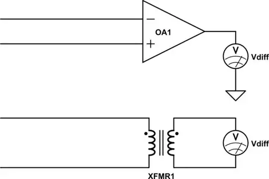
The idea that it is common mode comes from three-conductor cables, in which there is a shield wrapped around a pair of conductors that carry a differential signal. The signal is taken to be the difference between the conductors. Any potential between the two inner conductors and the shield is common mode. This is analogous to the parallel movement of the + and - inputs of a differential amplifier, with respect to ground.

In a two conductor cable in which the signal is the difference between the inner conductor and the shield, the meaning of common mode changes: common mode is the movement of both the shield and inner conductor. This is analogous to the + and - inputs of a differential amplifier where one of them is tied to ground. For common mode noise to occur, there has to be an issue with the ground that causes it to move.

There is probably confusion about this in some literature, due to authors mistakenly applying what they researched about differential lines to single-ended lines.

Although op-amps are often used nowadays to pick up the signal from a single-ended line, amplifiers that are used this way are no longer differential. The op-amp device is differential, but the circuit is single-ended. You can do the same kind of amplification with (for example) a common source/collector transistor stage: no diff amp needed.

Strictly speaking, the term "common mode" applies to differential lines and differential amplifiers, which have a contrasting "differential mode".

When we use the term "common mode" in the context of a single ended signal processing system, it refers to the signal's ground as being regarded as a nonideal ground which can move with respect to the ideal 0V reference, so that in a sense the amplifier has a differential mode (whether or not it is a differential op-amp, or a single-ended input stage).

Of course, a single-ended system is "differential" in the sense that any voltage quoted as absolute is actually a potential difference, and we can apply that to a diff amp. But that's not what we mean by "differential".

The key aspect of differential signaling is not the use of opposite signals. Differential signaling does not require opposite and equal signals. It works just as well if one of the conductors has no signal in it at all. The key aspect of differential signaling is the use of two signal networks, neither of which is ground, and which have equal impedances with respect to ground. This is what "balanced" refers to. Any common mode noise induced in the two lines sees the same impedance in each line and therefore generates the same voltages at the inputs, which are subtracted and canceled (somewhat imperfectly, resulting some given number of decibels of attenuation).

A single-ended system cannot be balanced, because its signal line requires an input impedance and the return line needs to have, ideally, a zero impedance to ground.

Kaz
  • 19,838
  • 1
  • 39
  • 82
4

When we define the common mode and differential mode currents, we get some relations like

\$ i_{\mathrm{comm}} = \dfrac{1}{2}(i_+ + i_-)\$

\$ i_{\mathrm{diff}} = i_+ - i_-\$.

Now you defined a different way to split up the currents on a coax, recognizing only these two types of current:

  1. currents flowing on the inner conductor, matched exactly by equal and opposite currents on the inner side of the shield (differential mode)

  2. currents that flow only on the outside of the shield

This implies that there's no current on the inner conductor that isn't matched by an equal and opposite current on the outer conductor.

Let's call the current on the center conductor \$i_c\$ and the current on the outer conducter \$i_s\$. And we'll define a positive current on either conductor to be going away from the source.

Now we must have \$i_s = -i_c + i_2\$ where \$i_2\$ is your 2nd category of current.

So, \$i_2 = i_s + i_c\$. And we see that, aside from a scaling factor of 2x, \$i_2\$ is just the same as the common mode current as usually defined.

The Photon
  • 126,425
  • 3
  • 159
  • 304
  • That's correct enough. However, if the OP tries to measure the differential mode \$i_{\rm diff}=i_c-i_s\$, as with the circuits they depicted, they'll find that what they'll get is \$i_c-(i_2-i_c)=2i_c-i_2\$. Thus, the differential amplifier does not entirely reject \$i_2\$, since that signal is really a mix of the differential and common modes. – Ilmari Karonen Jul 02 '13 at 10:42
  • That makes sense, but does \$i_2\$ have a name? It's relevant because this is commonly noise from external sources, much like the common-mode signal is usually noise on a balanced transmission line, and we'd want to reject it for the same reasons. – Phil Frost Jul 02 '13 at 14:32
3

Let me follow The Photon's notation and use \$i_c\$ and \$i_s\$ to denote the currents in the core and shield of the coax, \$i_{\rm diff}\$ and \$i_{\rm comm}\$ to denote the differential and common mode currents, and \$i_1\$ and \$i_2\$ to denote the two types of currents (core-in-shield-return and shield-only) in your question.

Now, any of these pairs of current measurements is sufficient to uniquely express any possible set of currents flowing along the cable. The problem is that, whereas the linear map $$(i_c,i_s) \mapsto (i_{\rm diff},i_{\rm comm}) = \tfrac12(i_c-i_s,\,i_c+i_s)$$ is orthogonal, the map $$(i_1,i_2) \mapsto (i_c,i_s) = (i_1,\,i_2-i_1)$$ is not, and thus neither is the combined map $$(i_1,i_2) \mapsto (i_{\rm diff},i_{\rm comm}) = (i_1-\tfrac12i_2,\,\tfrac12i_2).$$

Thus, whereas the common mode \$i_{\rm comm}\$ is indeed proportional to \$i_2\$ and independent of \$i_1\$, the differential mode \$i_{\rm diff}\$ is a mixture of the \$i_1\$ and \$i_2\$ modes. Or, to look at it the other way around, the \$i_1\$ signal is purely differential, but the \$i_2\$ signal is a combination of the differential and common modes.

In particular, this means that the differential mode \$i_{\rm diff}\$ is not orthogonal to the \$i_2\$ mode, and thus measuring the differential current using a transformer or a differential amp does not fully reject \$i_2\$.

So much for the mathematics. Now, if you do want to reject the \$i_2\$ current, you're going to need to measure something which actually is orthogonal to it. In your case, the obvious (naïve?) choice would be just the core current \$i_c\$, which in your system as you describe it simply equals \$i_1\$.

Ilmari Karonen
  • 832
  • 6
  • 13
  • I think that answers this question, but I'd like to know more about rejecting \$i_2\$: [Is it possible to reject noise traveling on the outside of a coaxial transmission line?](http://electronics.stackexchange.com/questions/71201/is-it-possible-to-reject-noise-traveling-on-the-outside-of-a-coaxial-transmissio) – Phil Frost Jul 02 '13 at 14:27