7

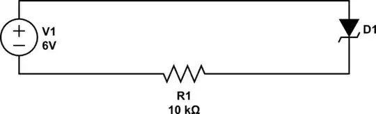
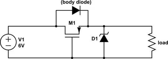
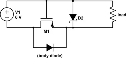
I have the following circuit (just the input portion of a larger circuit):

enter image description here

The 6V is coming from a wall wart or other 6 V source. The Schottky diode (UPS120) is there to guard against the input voltage coming in at the wrong polarity. The output is connected to a couple of LDO regulators, and the guaranteed maximum forward voltage (450 mV) of the UPS120 gives me enough headroom for the regulators.

However, I also need the full 6 V for a bias voltage elsewhere in the circuit. Although the wall wart I am planning on using is a switcher, my experience is the wall wart may go slightly above 6 V (e.g. 6.4 V) under little load so I added a 6 V Zener to make sure my bias voltage does not go above 6 V.

What happens though if the wrong polarity is applied to the input? My regulators are protected because of the Schottky diode. But what will happen to the Zener? Will it clamp to ground (ok) or go below ground (not okay)? In the latter case, how can I mitigate this?

JYelton
  • 32,302
  • 33
  • 134
  • 249
tcrosley
  • 47,708
  • 5
  • 97
  • 161

3 Answers3

5

If the input voltage goes negative, then the zener will be forward-biased, and will behave not unlike an ordinary diode. Your \$10k\Omega\$ resistor will limit the current.

schematic

simulate this circuit – Schematic created using CircuitLab

The voltage across D1 will be about 0.6V. The current is given by Ohm's law:

$$ \frac{6V-0.6V}{10K\Omega} = 0.54mA $$

That's not much current, so maybe it won't damage anything. You will have to decide, based on what's connected.

If that's not acceptable, then you could another diode to prevent all reverse current. But you say that the additional voltage drop would not be acceptable. You can eliminate this voltage drop by using a P-channel MOSFET instead:

schematic

simulate this circuit

When V1 is first applied, the body diode inherent in the MOSFET conducts, but soon this voltage appears at the load, and thus also between the source and gate of M1. This turns M1, shorting out the diode, and the only voltage drop you get here is due to the resistance of \$R_{DS(on)}\$ of the MOSFET, which will be very small.

If V1 is reversed, then the body diode will not conduct, and M1 will not be turned on, and there will be no reverse current (except the very small leakage through M1).

schematic

simulate this circuit

You can also do the same thing with an N-channel MOSFET in the ground return, but usually you don't want to disturb the ground reference for the load. If that's not a problem in your application, then go ahead and use an N-channel MOSFET, since they are easier to source. 2N7000 would work fine at the currents you have here.

Further reading: Reverse polarity protection

Phil Frost
  • 56,804
  • 17
  • 141
  • 262
  • Thanks for the circuits showing how to get rid of the diode voltage drop using a mosfet oriented with the internal diode in the forward direction. Hadn't seen those before. – tcrosley Jul 02 '13 at 04:29
  • When the supply voltage is reversed Pmosfet is off, then why do we need a zener diode –  May 06 '14 at 05:31
  • @Rukh It's not strictly necessary, but it does give you some overvoltage protection. A MOSFET gate is very sensitive to overvoltage, even very brief transients. – Phil Frost May 06 '14 at 11:30
  • If you have a TVS from the Source to Ground which will (assuredly) clamp before the FET's max rated gate-source voltage, one would not need the zener + resistor would they? – KyranF Nov 02 '16 at 04:57
  • @KyranF If it has sufficiently fast transient response, I suppose not. – Phil Frost Nov 03 '16 at 01:48
  • @PhilFrost well i'd hope so, it's a TVS (fast surge/spike suppressor)! Obviously continuous over-voltage condition is a no-no, and a fuse would be in order if that was expected to be an issue – KyranF Nov 03 '16 at 01:52
  • @KyranF There's stray inductance to consider, which may be relevant depending on layout. A TVS at the other end of 10 meters of cable is probably of not much help. – Phil Frost Nov 03 '16 at 01:56
  • @PhilFrost yeah, the TVS in that scenario is at the input connector along with the P-FET for reverse polarity protection.. – KyranF Nov 03 '16 at 02:00
4

It will go below ground one diode drop but the 10k resistor will limit the current into the zener and hence into the circuit that may be damaged so, the only question you have to ask is "how much current can my input take before it is damaged".

My gut feeling is that on most devices (MCUs op-amps and the like) 10k from +/- 6V is not going to damage anything but the most exotic of devices so, you are probably going to be OK.

Check your data sheet about how much current you can stuff up an input.

Andy aka
  • 434,556
  • 28
  • 351
  • 777
  • The input goes into both a microcontroller input and an external comparator via a voltage divider. The zener has a forward voltage drop of 0.9v (I couldn't find a 6v one lower than that). After the voltage divider, this becomes 0.4v, and a maximum current of only 1 uA. The minimum input for both the microcontroller and the comparator is -0.3v. Even though the input might go down to -0.4v, because of the low current I am guessing I will be okay. Of course this is not normal operation, it is only if the input polarity somehow got reversed, which I am assuming is a very unlikely situation. – tcrosley Jul 01 '13 at 21:39
  • There should be some specification for maximum current allowed into inputs and I'd bet this isn't exceeded given what you said. – Andy aka Jul 01 '13 at 21:42
0

A Zener typically needs 5 mA to develop its Zener voltage. With a 10 kOhm resistor, that's unlikely to happen. Thus, the Zener can't do much to regulate voltage.

Similarly, if you connect a reverse voltage across the system, the Zener will conduct like a normal forward diode with some amount of forward drop -- thus the "6V" output will become something like -0.5V.

A Schottky diode will typically have a forward drop of betwen 0.3V and 0.6V. Thus, the voltage your regulators see will be more like 5.4V. If they have a drop-out of 2.0V (like the 7805) or 1.2V (like the 1117) then the highest voltage you can generate form them will be 3.4V or 4.2V, respectively.

Finally, regarding your schematic, to make it prettier for people to read:

  • Add component designators (D1, D2, R1, etc) to the schematic, and net labels, so it's clear what components are being talked about.
  • Turn off display of "origins" for your components and texts, as the plusses get in the way.
  • In Eagle, there is an "export as bitmap" which makes cleaner images than just doing a screen capture.
Jon Watte
  • 5,650
  • 26
  • 36
  • I'll look into reducing the value of the 10k resistor to develop a higher current through the zener. Re the forward drop, I am using an ADP3338AKCZ which has a typical dropout voltage of 0.19v. Thanks for the other suggestions. – tcrosley Jul 02 '13 at 00:14