6

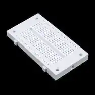
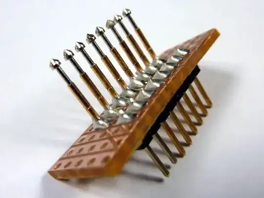
One of my components for a prototype lies on a breakout board. The rest are connected on a breadboard.

How can I neatly connect the leads on the breakout board (seven in the picture) to rails/holes on the breadboard? I'd prefer not to solder, since I'd like to reuse the breakout board.

enter image description here enter image description here

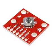
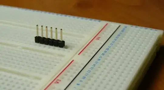
Would simply putting the breakout board on a 1x7 header work?

Andreas
  • 713
  • 2
  • 13
  • 21

4 Answers4

3

One way that might work is to use clip-on or "grabber" test leads:

Mini Grabber Test Leads

You can find these inexpensively on eBay or from electronics suppliers. (I found the image at Circuit Specialists.)

On the breadboard, insert some pin headers or just use some short jumpers to clip the lead to.

Pin Headers on Breadboard

Edit:

In response to your edit, putting the PCB on a 1x7 header would work if

  • You are soldering the pin header to the PCB. If it's loose, you'll be fighting loose connection issues.
  • The holes on the breakout board are spaced at 0.1 inch, matching the pitch of the breadboard and header. (It doesn't look like they are, but I could be wrong.)
JYelton
  • 32,302
  • 33
  • 134
  • 249
  • Seeing that this is a SparkFun board, I'm most certain that the pitch is indeed 0.1 inch. – abey Jul 01 '13 at 20:45
  • Thanks! I'll try to get my hands on some clip-on cables. – Andreas Jul 01 '13 at 20:45
  • @abey: Yep, they fit well. I'm worried about the looseness though, and I don't want to tie the breakout board up forever by soldering it. – Andreas Jul 01 '13 at 20:47
  • 2
    Soldering the header to the breakout board is most often the best way. You should get a good enough connection to the breadboard and if you ever need to desolder the header, it's not too difficult. When you heat the pin enough to desolder it, it will melt the plastic part and you will be able to remove one pin at a time with pliers (thereby killing your header). – abey Jul 01 '13 at 20:50
  • I usually push the pins down a bit (works best with a vise), so that the plastic part is approximately in the middle. – starblue Jan 04 '17 at 20:29
3

I would solder the header to the breakout board with the pins pointing down.

The luxury version is to use turned pin header, with smaller round pins.

starblue
  • 6,462
  • 2
  • 21
  • 35
  • I was having connection issues with an electret microphone breakout board when I tried to "pin" it to the breadboard with jumper wires. Soldering a header onto the breakout board solved the problem. – yoyo Jan 04 '17 at 05:06
3

Aside from test clips, you could use pogo pins. enter image description here

Passerby
  • 72,580
  • 7
  • 90
  • 202
2

Another alternative is first to solder a 0.1" 1x7 header facing up on your breakout board as others have suggested, and then use these female-male cables from SparkFun to connect to the breadboard. The advantage of this method is you don't have to waste 7 rows of holes on the solderless breadboard; you can insert the male ends anywhere as needed by the circuit.

enter image description here

The female ends fit perfectly over the pins on the header, and the males end fit into the breadboard just as well.

Just go to Sparkfun and search for "jumper wires".

tcrosley
  • 47,708
  • 5
  • 97
  • 161