3

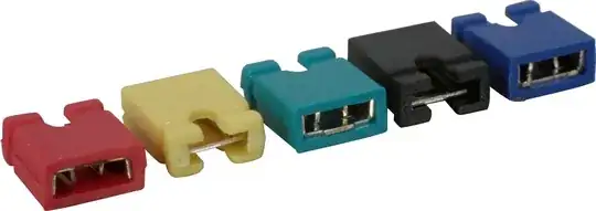
Two settings on a system I've got can be changed using jumpers. This is the connector and the pin description:

enter image description here enter image description here

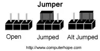
There seems to be three pins needed to choose between ON and OFF, but how? Do I set them to high/low in some pattern? The documentation is very sparse so I assume this is some standard interface, but I couldn't google it.

5.3 Jumpers description

Please note that the two jumpers on the board are PTH (plated-through hole) type and should be easy to mount/dismount.

5.3.1 TARGET jumper

TARGET jumper controls the powering of the target board. If it is in position ON (check the diagram on the back of the plastic cover) it will provide either 3.3V or 5V to the target board (depending on the position of the POWER jumper) The default position is OFF.

Andreas
  • 713
  • 2
  • 13
  • 21
  • In the pictured example, it looks like the settings are "OFF" and "5V". – Phil Frost Jun 27 '13 at 13:55
  • @PhilFrost Yep. When I asked the question, I had no idea how jumpers worked and didn't realise that the actual things that connect the wires were already there. – Andreas Jun 27 '13 at 14:16

3 Answers3

4

(That looks like an AVR programmer)

The jumper is a tiny plug that connects two pins.

enter image description here

You put the jumper either on the left two pins or on the right two pins. The middle pin is a common pin.

enter image description here

In your case the jumpers are being used as a SPDT switch that can't be accidentally moved.

To change the selection, pull off the jumper and push it into the alternate position.

This applies to each group of three pins

RedGrittyBrick
  • 14,602
  • 5
  • 37
  • 77
  • Aha, thanks. Well spotted, it's an AVR-ISP-MKII. – Andreas Jun 27 '13 at 11:20
  • It looks like the OFF and 5V pins are already connected. That can be seen in the photo, too. Is that what is meant by "default position"? Do I have to cut it before I connect a jumper? – Andreas Jun 27 '13 at 11:23
  • Never mind, I get it! I didn't realise that there were _already_ jumpers on the pins, and that I can remove them. – Andreas Jun 27 '13 at 11:24
  • No you don't need to cut anything, you just pull off a jumper and push it on in the other position. As I understand it, if your target board doesn't provide a voltage reference on the main connector, you have to tell the programmer what voltage to use for programming. I think the "off" position means the board doesn't provide a reference voltage, in which case the programmer uses the lower jumper position to decide what voltage to zap your AVR with. – RedGrittyBrick Jun 27 '13 at 11:27
  • 1
    "Do I have to cut it...": You just missed the opportunity to be the first person to actually cut a jumper instead of just unplugging it :) – Rev Jun 27 '13 at 13:24
1

Jumpers are metal clips that short circuit two pins. The pins select which parts of the circuit are connected.

JIm Dearden
  • 18,926
  • 30
  • 40
1

Jumpers are used in order to enable the user to change setting simply moving it.

The central pin is common, so if you want to set the device ON the jumper must stay in the first two pins, if you want to set the device OFF the jumper must stay in the last two pins. The same is true for the power supply (5V left, 3.3V right). In every case you must connect the jumper, otherwise the selection input is floating and it can't work correctly.

Oceanic815
  • 1,179
  • 1
  • 11
  • 19