1

I've got an AVR ISP MK2 that I'm going to program an ATmega328P with using ISP. This is the schematic of the 2x5 pin ICSP connector:

enter image description here

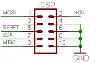
First: Does this mean that I am supposed to connect #2 to +5V and #{4,6,8,10} to ground? Why does the programmer need another power supply when it already has USB?

Second: My plan is to cut the 10-lead flat cable up and solder the individual leads for my prototype. How can I know which lead corresponds to which pin?

Andreas
  • 713
  • 2
  • 13
  • 21
  • Post the complete schematic. – Leon Heller Jun 26 '13 at 16:42
  • 1
    @LeonHeller - this is a standard interface, so the schematic of a particular implementation would essentially only be relevant if it turned out to deviate from the original intent of the connector. The question should preferably be handled in the general case so that answers are more widely applicable and less localized to a particular person's project. – Chris Stratton Jun 26 '13 at 17:15
  • @Andreas - programmers often want to know the voltage of the target circuit so that their output drivers use the proper levels. Some programmers can also power the target (you'd have to check the specs for the 10-pin ISP to see if that is the case, I don't know off the top of my head). For figuring out cabling, a pragmatic choice is to examine an IDC ribbon to header connector, or find one in a catalog and click through to its data sheet. – Chris Stratton Jun 26 '13 at 17:17
  • @ChrisStratton Thanks! If you think the question could be better, you're welcome to edit it. About examining the IDC connector: how would I know that the schematic isn't "upside-down"? – Andreas Jun 26 '13 at 17:38
  • @Andreas - it doesn't matter if the schematic is upside down or mirror or flipped, as a schematic is not intended to represent physical geometry (though if working towards making a simple board it can sometimes be useful to draw it that way for planning purposes). For determining the geometric location of numbered pins, you need the data sheet for a connector of this type, or a physical example to examine or investigate with a continuity meter. Typically pin one has a marker such as a triangle on the plastic, or a red stripe on the cable, or a square PCB pad instead of round, etc. – Chris Stratton Jun 26 '13 at 17:43
  • @ChrisStratton Thanks, I didn't know that! One of the leads is red. I'll assume that it's #1 and that the others follow in order, and see if it works. – Andreas Jun 26 '13 at 17:50
  • Read the datasheet for your microcontroller! – Phil Frost Jun 26 '13 at 17:54
  • 2
    @PhilFrost How is the microcontroller relevant? Or did you mean the programmer? I knew which pin on the MCU is which, but not which lead on the flat cable is which. – Andreas Jun 26 '13 at 17:57
  • Indeed, it's not relevant, as none of the pins you had questions about would be covered on the MCU data sheet. – Chris Stratton Jun 26 '13 at 18:04
  • The microcontroller datasheet is relevant, because you need to know which pin does what. And, I happen to know that the Atmel datasheets do contain a section on ICSP. – Phil Frost Jun 26 '13 at 18:05
  • @PhilFrost - the question is not about understanding ISP in general, but about understanding certain details of the 10-pin ISP header. That would not normally be on a data sheet, but in a separate document (note the manual for this 3rd party programmer is linked). It's possible Atmel tosses the 10-pin spec onto some MCU data sheets for fun, but I can't recall having seen it there, and it's not where I'd normally expect to find it. If I were instead curious about how the reset pin is used in ISP, then I'd expect to see at least a little coverage on the data sheet, or pointer to another doc. – Chris Stratton Jun 26 '13 at 18:07

1 Answers1

2

The AVR-ISP mkII does not supply power to your circuit. As such, it is incumbent on you to supply power to that pin in-circuit so that the programmer can sense the target voltage. Cutting the connector is an aggressive approach... I would advocate that you just buy a 2x5 male header and solder wires to it.

I have to modify this answer back, I thought it was talking about the Atmel product, not the Olimex clone. From the datasheed:

5.3.1 TARGET jumper TARGET jumper controls the powering of the target board. If it is in position ON (check the diagram on the back of the plastic cover) it will provide either 3.3V or 5V to the target board (depending on the position of the POWER jumper) The default position is OFF.

As always read the manual first

vicatcu
  • 22,499
  • 13
  • 79
  • 155
  • Thanks! I've got a 2x5 header, i.e. 2x5 pins held together by plastic. I still find them too close to solder, though. I could have connected it directly to my breadboard if it was a 1x10 header, but can't with the 2x5 due to the connections between the holes in my breadboard. Do you know any type of connector that would work for me? – Andreas Jun 26 '13 at 17:43
  • If you just want to get going, the wires you are using on your breadboard will probably plug right into the female cable connector - it's obviously precarious as they will fall out again easily. You may be able to buy a cable from a female header to a 10-pin DIP plug (or at least a larger version such as 14-pin) which you could carve down. Wire wrap wire and tools are also good for such connections, especially if you back up the short wrap (on PCB, rather than wire-wrap length pins) with a little solder. – Chris Stratton Jun 26 '13 at 17:49
  • If you can still find a 10-pin wire wrap length header, the tail ends of the pins would be long enough to carefully bend doglegs out to .3" spacing into, giving you something breadboard compatible. – Chris Stratton Jun 26 '13 at 17:51
  • It still isn't clear to me. If TARGET is OFF, the programmers does NOT supply power. Does this mean that the 5V and GND pins (on the programmer, not the MCU) should not be connected, or that they should be connected to the same 5V and GND as the MCU is? – Andreas Jun 27 '13 at 10:58
  • @Andreas It's simply a matter of whether the power is *supplied* by the programmer or not. There are two jumpers, TARGET and POWER. If you set TARGET to the on position, then POWER determines whether the board provides and signals 3.3V or 5V. If you set TARGET to the OFF position, the POWER jumper is irrelevant since the programmer is not sourcing power in that case. See section 5.3 of the manual. I would connect the GND pin and 5V pin of the ICSP header to the analogous nets in your circuit though, just make sure you don't apply power to your circuit separately if TARGET is set to ON. – vicatcu Jun 27 '13 at 12:00
  • Thanks! (I recently asked [this similar question](http://electronics.stackexchange.com/questions/74264/how-should-power-be-supplied-for-in-system-programming) for some clarification) – Andreas Jun 27 '13 at 12:03
  • @Andreas please note I added a sentence to my comment after you responded. – vicatcu Jun 27 '13 at 12:04