7

I'm reading up on A Simple Radio Receiver. I have a question about this image:

enter image description here

The signal from the antenna (perhaps a few tens of microvolts, or hundreds for a nearby transmitting station) is introduced to the LC circuit either through a small capacitance, or, as in this case, by means of a second coil L2 wound on top of L1, with its other end connected to earth. This behaves like a transformer - currents flowing in L2 generate a changing magnetic flux which cuts L1 and induces an emf in it.

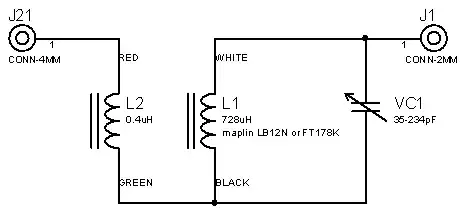
I don't understand why L2 is needed. It forms a transformer with L1, to "cut L1 and induce an EMF in it". What is meant by 'cutting' in this case? And, when they need EMF in L1, why not just connect it to the antenna input directly? Like this:

schematic

simulate this circuit – Schematic created using CircuitLab

Sorry for the ugly schematic, it would've be too large otherwise.

Anyway, why is a transformer needed in this crystal radio set? I actually built a crystal set without a transformer, with this circuit:

enter image description here

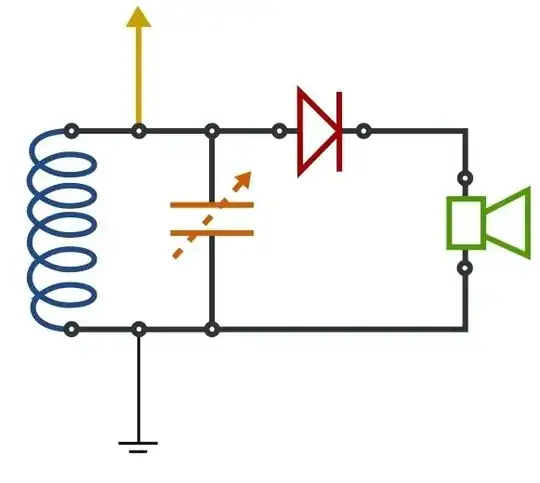
I also added a 100n capacitor parallel to the crystal earphone.

Why would or should I use a transformer instead of going into the LC circuit immediately?

4 Answers4

6

Do or Don't - Using a transformer or leaking antenna signal to the tuned circuit via a small cap really does work. By work I mean it makes the tuned circuit formed by L1 and C1 very much more resonant and this means channel selectivity and higher signals.

What about the antenna? The antenna impedance will be quite low and "resistive" and this is not ideal for connecting directly across the tuned circuit formed by L1 and C1 - it will dampen down the resonance and make selectivity poor and signal amplitude smaller.

Here is what I mean: -

enter image description here

I have selected L1 to be 100uH and C1 to be 220pF - this forms the basic tuned circuit. I have leaked onto the tuned circuit via a 33pF capacitor an input signal from a 50ohm source. In the middle top of the picture there is a yellow label. This says 1.001MHz and 32.93 - the 32.93 is actually dB of gain from output to input. Here is the simple circuit if you want to recreate it: -

enter image description here

32.93dB of gain is a slight exaggeration - 6dB will be lost in the 50ohm of the antenna so gain is actually 27dB and in real terms this is a voltage magnification of 22. I've used 50ohms to represent the antenna resistance which is a compromise value between 37ohm for a quarter wave dipole and the 73ohm for half wave dipole. I haven't bothered to introduce the reactive elements of either antenna for simplicity. They won't affect the general idea.

Take a look at how selective the response is: -

enter image description here

At 1.001MHz the peak is 32.93dB. At 1.011MHz the amplitude has fallen by 16dB and this is a decent selectivity for an AM receiver based on one tuned circuit.

In practice there will be more losses that need to be taken into account, namely earphones, diode etc. but if you start off with the right focus on getting decent selectivity and gain you might get a decent working xtal set.

Without the coupling coil or leakage cap you'll get at best 0dB gain and poor selectivity not 27dB gain and good selectivity.

Andy aka
  • 434,556
  • 28
  • 351
  • 777
6

There are three advantages to driving the resonant L-C tank via tranformer coupling than directly from the antenna:

  1. It changes the impedance. The impedance of the signal coming from the antenna is probably in the 50-300 Ω range. Crystal radios are usually listened to with high impedance headphones, usually around 2 kΩ. Having a 100 Ω source driving a 2 kΩ load is inefficient, which ultimately means lower volume.

  2. The detector diode drop is a smaller fraction of the output voltage. The transformer steps up the voltage, making it higher than what comes out of the antenna directly. The forward drop of the dector diode is fixed, so it is less relative to the signal after that signal has been increased in voltage by the transformer. This means lower strength radio stations will still produce some output, and the output you get will have less distortion.

  3. Better selectivity. The relatively low impedance of the antenna dampens the resonance of the L-C tank circuit. Another way to say this is that it lowers the Q of the resonant circuit. This means its resonant peak is more spread out, which means that the radio can't be tuned as well to a single station. The effect is that strong stations will appear to spill over into nearby frequencies.

Olin Lathrop
  • 310,974
  • 36
  • 428
  • 915
2

L1 is the primary coil of an RF transformer. This is magnetically linked to the coil L2 and steps up the voltage received by L1 (and aerial) by the turns ratio of the coils giving a larger voltage signal. The larger voltage signal helps to overcome the turn on voltage of the detector diode making the set more sensitive. It also helps with impedance matching between the aerial and the resonant circuit (L1 VC1).

What is being 'cut' by the conductors (wires) of L1 is the high frequency magnetic field produced by L2. A conductor in a changing magnetic field will have a voltage induced in it (see Faradays laws).

Yes you can build a crystal set by directly connecting the aerial to the LC tank circuit but you will find it is not as sensitive or as 'sharply tuned' as this version.

JIm Dearden
  • 18,926
  • 30
  • 40
  • I understand that, thanks. Does this also mean that with a transformer you'd be able to use a normal diode with a 0.6 threshold voltage? (You'd lose the sensitivity, but it's an easier to find part.) I saw the site I linked to used an OA47, which is a germanium diode. –  Jun 26 '13 at 09:43
  • 1
    @CamilStaps The signal strength is very low so if you used a silicon diode (0.6) you would lose any advantage of boosting the voltage. When I built these many moons ago we could easily get germanium diodes.The originals used a sharp metal point onto a crystal of galena (lead sulphide) - a point contact diode - hence the name crystal set. A good modern substitute for the Ge diode would be a Schottky diode - 0.2V forward drop. – JIm Dearden Jun 26 '13 at 09:51
0

You do not need to use a transformer but it is convenient. If you increased C by 10 and decreased L by 10 the resonant frequency would stay the same but characteristic impedance goes down by 10. This would not be convenient if C had to be variable.

JYelton
  • 32,302
  • 33
  • 134
  • 249
Autistic
  • 14,235
  • 2
  • 27
  • 65