In the circuit the relay is controlled from a manual switch on a 12v bus. I can't understand why you would want to add the extra components of the transistor and diodes to the circuit? ie why are D4, R1, T1, D1 needed? Thinking about cost and component count here.
-
Without knowing the spec of the relay & the switch it's hard to guess. Some switches may be rated below the relay coil's current requirement. – John U Jun 25 '13 at 13:30
-
2Clean up the schematic, especially before imposing it on all of us here. -1 for sloppiness. – Olin Lathrop Jun 25 '13 at 13:32
-
I can't even guess what you think D3 does. D1 might be intended to catch the flyback pulse from the relay coil, but if so, it's in the wrong place. If not, I can't guess what it's supposed to do either. – Olin Lathrop Jun 25 '13 at 13:35
-
@OlinLathrop ha I agree on the schematic, but I took this over from another engineer. I was told to look into updating the schematic. hence I am trying to fully understand it first as well. – EE_PCB Jun 25 '13 at 13:42
1 Answers
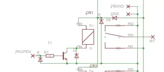
The transistor and the resistor might be needed because the input can not supply enough current to drive the relay. D4 protects the transistor from a negative voltage at the input.
D6 protects the transistor from a negative power, and prevents spikes to enter the power rails.
A relay that is switched off produces a current pulse that must be dissipated somewhere, otherwise it will destroy the transistor. D1 could be intended to protects the transistor against this pulse, but IMO it is placed wrong: the diode should be in parallel with the relay coil.
I can't see any purpose for D3, unless it has something to to with components connected to the vertical wire that are not shown.
All in all this looks like a circuit produced by a committee with too much open agenda's and some closed ones too.

- 48,407
- 1
- 63
- 136
-
If the supply for the transistor is coming straight from a 12vdc bus then there would be no need for the transistor or extra circuitry that I can see. I guess I just wanted to confirm this. Thanks! – EE_PCB Jun 25 '13 at 13:45