11

I have an SFH235 ir photo-diode (which datasheet can be found here) and only basic knowledge of electronics.

I want to connect the photodiode to an Arduino (the grand-plan is to add an ir diode and build a distance sensor).

I understand that photodiode produce current, and it produces more current the more intensive the light that falls on it.

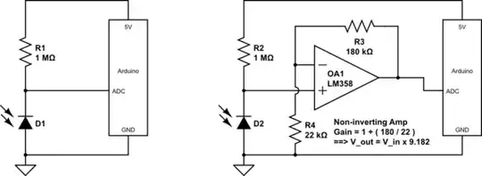
I have seen schematics that connect photodiodes the same way that photoresistors are being connected. Others connect it to an "opamp"(why?) And that are also those articles that say I need to amplify the current. I have also seen capacitors added into the circuit.

Which is the correct way for my application? How can I connect the photodiode to the analogue input of Arduino (which measures voltage)?

Artium
  • 287
  • 1
  • 3
  • 13

2 Answers2

11

The simplest way to connect a photodiode (even an LED can be used in this way as a photosensor) is as below:

schematic

simulate this circuit – Schematic created using CircuitLab

Note that the photodiode is reverse biased through the 1 Meg resistor R1. The photocurrent generated by the diode opposes the flow of leakage current through this reverse biased diode, said opposition increasing with more light on the diode junction. The voltage at the junction point thus rises in voltage with increase in light.

The schematic on the left will have fairly low voltage at the ADC pin. To increase this voltage, an op amp can be used as a non-inverting amplifier, as shown in the schematic on the right. In the example shown, this gain is Gain = 1 + (R3/R4) = 9.9182.

This voltage gain results in a greater reading at the ADC pin, potentially making use of a greater part of the ADC's input voltage range.

Other applications of op-amps for photodiodes include:

  • as a transimpedance amplifier, to directly amplify the photocurrent, without use of a biasing resistor
  • as a voltage follower (unity gain buffer) for the voltage divider formed between diode and biasing resistor

Note:
One must ensure, though, that the voltage after amplification does not exceed the 5 Volt supply. If the op-amp is powered from the same 5 Volt supply as the Arduino, this is automatically taken care of, as the op-amp's output gets clipped at its upper supply rail, or even lower if the op-amp is not a rail-to-rail type.

Anindo Ghosh
  • 50,188
  • 8
  • 103
  • 200
  • If I use the simple way (left schematic) how can I calculate the input voltage on the ADC? How do I choose a value of R1? What confuses me is that when I measured voltage, current and resistance of the photodiode, all three changed with higher ir light intensity, I was thinking that only the current value is a parameter I can use to represent ir intensity. – Artium Jun 24 '13 at 19:02
  • 2
    @Artium You would need to actually measure the voltage using a high impedance method (such as a 10x, or better, 100x probe on an oscilloscope ). Similarly, just start with R1=1M, then try 470k and 2.2M, to see which works best. The act of measuring the voltage or current would change the value, since the photocurrent magnitude is really very small, and the leakage through a typical inexpensive multimeter probe would drain away a lot of those femtoAmperes. – Anindo Ghosh Jun 24 '13 at 19:43
  • So for the implicit input rails on the op-amp in the circuit at right, would the positive rail be connected to 5V and the negative rail to ground? – geometrian Jan 12 '18 at 08:13
  • 2
    @imallett Yes, the implicit _supply_ rails would be connected to +5v and ground, as you say. – Anindo Ghosh Jan 13 '18 at 09:02
  • 1
    "The voltage at the junction point thus rises in voltage with increase in light." Using the circuit at left (with battery instead of Arduino; measuring voltage at junction point relative to ground with multimeter), I get exactly the opposite. – geometrian Feb 08 '18 at 05:14
2

As Members have said above, the Voltage & Current from Photo-diodes can be very small, especially so with IR. The OSRAM SFH203PFA shown for Instance can make 0.25-0.35 under Ambient or Mains lighting, but without Bias makes only a 0.003 3 Millivolt wave hit by IR Laser on my Phillips Oscilloscope. Amplification using an Op Amp works for me.

Dave Bond
  • 21
  • 1