18

Given a circuit like this:

schematic

simulate this circuit – Schematic created using CircuitLab

What's the importance of R1? One can guess that it's to make the output impedance of BUF1 equal to the impedance of the transmission line, but why is this important? What happens if R1 is omitted? How does what's on the other end affect this? Maybe it's a matched load, open, or short. Maybe it's a transmission line with discontinuities in it.

Phil Frost
  • 56,804
  • 17
  • 141
  • 262
  • You can ignore the Telegrapher effects of R1 if prop. delay is < 5% of rise time at 2cm/ns or 0.5ns/cm prop. delay. Then the output is simply a voltage divider with load at any frequency unless you are concerned about <1% ripple or phase shift or the prop delay itself. Otherwise there is a reflection coefficent that distorts the waveform starting with ringing on step waves. – Tony Stewart EE75 Jun 16 '19 at 06:15

4 Answers4

16

The idea is that signals propagate at a finite speed, that is to say a certain signal takes t time to get from one end of the transmission line to the other line. The cable also has some intrinsic capacitance/inductance per unit length, which can be approximated with a characteristic impedance (assuming loss-less):

\begin{equation} Z_0 = \sqrt{\frac{L}{C}} \end{equation}

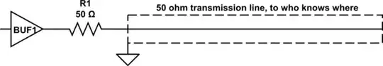
This is the impedance initially experienced by the source when the signal changes, with the signal level acting like a voltage divider circuit between R1 and Z0: \begin{equation} V_s = V_{in} \frac{Z_0}{R_1 + Z_0} \end{equation}

When the signal propogates to the end of the cable, it will realize that there's nothing to dump the signal energy into. The signal must go somewhere, so it bounces off the far end and returns to the source. When it reaches the source, the source voltage will be twice the original \$V_s\$, which will flow back through R1 to the source.

If \$R_1\$ = \$Z_0\$, \$V_S = V_{in}\$ and the entire transmission line has reached steady state because no more energy can be injected into or absorbed from the line. This is ideal because the line has reached steady state in ~2t (one t to get to the target, and one t to get back to the source).

If \$R_1\$ is too large, \$V_S\$ will still be larger than \$V_{in}\$ so the source will continue to dump energy into the transmission line, and the transmission line's voltage will slowly step up as the signal bounces back/forth.

If \$R_1\$ is too small, \$V_S\$ will overshoot when the signal gets back. In this case, a falling edge wave will propagate down the line because the source is trying to absorb the excess energy pumped into the line, and again the voltage will bounce back/forth till steady state is reached.

In the latter 2 cases the target voltage could bounce above/below a certain digital logic level multiple times so the receiver could get false data bits as a result. This could also be potentially damaging to the source because the reflected signal may rise induce excess stress on the source.

Now what happens if we attach something to the other side, like a resistor \$R_2\$?

Now the target can absorb energy, and only a fraction of the original signal is reflected. If \$R_2 = Z_0\$, we again have matched impedances and no signal is reflected.

If \$R_2\$ is too small/too big, we'll end up with similar reflection signals as above, except the signal is inverted.

Using \$R_1 = Z_0\$ can still be used to prevent repeated bouncing, but the steady state signal voltage will be the result of the voltage divider between R1 and R2. If \$R_2 = Z_0\$, there is no reflection so the value of R1 doesn't matter. We might as well pick R1 = 0 so the target voltage is the same as the source voltage. As supercat pointed out, you could also have the source drive a signal twice the magnitude the target is expecting and still use \$R_1 = R_2 = Z_0\$

I wrote an online transmission line simulator to play around with which demonstrates source termination. I found it useful for visualizing these signal propagation waves along the transmission line. Pick a large enough R2 and you can approximate an open, like the case you have. This only models loss-less transmission lines, but is usually accurate enough.

sparaps
  • 59
  • 8
helloworld922
  • 16,600
  • 10
  • 54
  • 87
6

In terms of signal integrity (measured by step response at the receiver side) the three configurations are identical (Zsource - Zload):

1) 50 Ohm - infinity (source termination)
2) 0 Ohm - 50 Ohm (load termination)
3) 50 Ohm - 50 Ohm (termination at both ends)

However, in the 3rd variant there is a 50% decrease in amplitude. So, from practical standpoint the 3rd option should be avoided unless there is a compelling reason to do so.

Disclaimer: this covers single wire point-to-point ideal cable one direction communication between the source the receiver. If there is a junction on the way, then it may make sense to use dual termination - I didn't think about it.

Sergei Gorbikov
  • 1,723
  • 3
  • 25
  • 29
2

Ok, here's the long but overly generalized description of what's going on...

The impedance of the transmission line (a.k.a. trace) is 50 ohms, which means that as the signal travels down the cable it looks like a 50 ohm load to the driver. When it hits the end of the trace, it reflects back and causes parts of the trace to temporarily reach a much higher/lower voltage than it should. We call this overshoot and undershoot.

With the 50 ohm source resistor, the resistor plus 50 ohm trace forms a voltage divider (div by 2). Just before the signal hits the end, the signal at that location is 50% of the needed amplitude. Just after the signal hits the end, the reflection combines with the 50% original signal and results in a perfect 100% amplitude signal. The reflection travels back to the source resistor where it is absorbed.

A receiver located at the very end of the trace will see a mostly perfect signal edge. But a receiver in the middle or near the resistor will first see a 50% signal and then a 100% signal. Because of this, source termination is only used when there is only one receiver and that receiver must be located at the end of the trace.

If the resistor does not match the impedance of the wire/trace/cable then the voltage divider is not 50%-- which results in an imperfect match and the reflection could cause issues.

  • 2
    Using source termination alone isn't great, but it's pretty common to use both source termination and load termination, and simply start with a signal that's twice as strong as what should be received at the far end. Using both source and load termination will allow a signal to propagate cleanly even if there's a section of the transmission line where the impedance isn't right (e.g. at a junction of two cables). If one used load termination alone, the signal reflecting off that imperfection would be rereflected at the source and appear some time later at the load. – supercat Jun 21 '13 at 23:48
  • 2
    @supercat so, am I right in thinking that source and load termination is great for low power signals, because it's more robust against transmission line non-idealities, but if you wanted to transfer a lot of power (RF transmitter into an antenna that should be matched, for example) then you would want \$R_1=0\Omega\$ to keep losses to a minimum? – Phil Frost Jun 22 '13 at 00:40
  • 1
    I guess the assumption here is that the load impedance at the other end of the line is very large, right? That wasn't really true in the situations I had in mind (probably I imagined an antenna as the load), but I guess it's the norm in digital circuits. Am I right? – Phil Frost Jun 22 '13 at 01:00
  • @supercat Actually, source termination alone (with only one load) is ideal. The quality of the signal is identical to a properly done end termination. Using source + end termination is only common for running over long cables when you have more control over the TX voltages (which is rare). –  Jun 22 '13 at 02:07
  • @PhilFrost If you only have one load, source termination is better than end termination because you do not have the additional power draw when the signal is not switching. A 50 ohm end termination could be consuming up to 60 mA even when the signal is not doing anything. –  Jun 22 '13 at 02:11
  • @DavidKessner I guess we are talking about digital electronics where \$R_L\$ can be very large, but I was thinking more about RF, where the antenna is probably matched to the transmission line, and you want it to consume the power. – Phil Frost Jun 22 '13 at 02:21
  • @PhilFrost Given that, I agree with where you are coming from. –  Jun 22 '13 at 02:22
  • 1
    @DavidKessner: If there is one load, and if one can reasonably expect that there won't be impedance mismatches on the line between the source and load, source-only termination is good. Video seems to commonly use 75 ohm source and load impedance, though I've seen a devices do all sorts of weird things in such a fashion that some combinations work together and others don't. – supercat Jun 22 '13 at 19:17
  • 1
    @supercat Yeah, analog video over coax is the most common one that uses double-termination. Gigabit Ethernet also uses double termination, but more because each pair of wires is bidirectional. Modern interfaces that use differential signaling (HDMI, PCIe, SATA) use end termination, but mostly because they use current mode signaling. I honestly haven't done the simulations of double-termination w/mismatches because other than for analog video I just haven't needed to. I'll play around with it and see what happens. –  Jun 22 '13 at 19:38
1

R1 is not important providing that the transmission line is terminated correctly. I drive lines like this a lot and get decent reception at the far end of the transmission line but it must be terminated correctly.

Andy aka
  • 434,556
  • 28
  • 351
  • 777
  • R1 is the termination, it's called source termination. But if you have proper end termination then R1 will make things worse. If R1=50 and you have end termination (50 ohms) your entire signal will be attenuated by 50%, which isn't good. So obviously R1 is important. –  Jun 21 '13 at 22:20