I am trying to wire a 2 bit adder and a Multiplier on my breadboard. I have the 2 bit adder somewhat done, but dont know where to start on the multiplier. I need help reading circuits and translating them to the breadboard. My main issue is figuring out where the outputs and inputs go. I know the in and outs are at pin 3, 6, 8, and 11 on the 7408 chip, but i just feel im doing it wrong. Help! 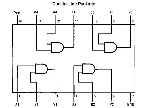
Asked
Active
Viewed 9,431 times
4
Josh
- 459
- 1
- 5
- 13
Ryan Cooley
- 41
- 1
- 2
-
Can you give a little more information on what parts you're using and maybe what circuit schematics you need help reading? – Angelo Stavrow Jun 20 '13 at 17:38
-
Surely a 2-bit multiplier needs two separate 2-bit inputs for the operands and a 4-bit output for the result? Or are these serial input-serial output multipliers? – Dilip Sarwate Jun 20 '13 at 17:38
-
Hopefully the schematic I uploaded will clear things up. – Josh Jun 20 '13 at 17:52
-
This question might help you get on the right track: http://electronics.stackexchange.com/questions/47276/combinational-logic-design-truth-table-and-k-map-question – The Photon Jun 20 '13 at 20:32
-
7408 implements AND gates... not adder. – travisbartley Jun 21 '13 at 02:54
1 Answers
4
Well I'm not sure exactly what you're asking, but I'll try to be of some help.
First, if you know how K-maps work, it'll make circuit simplification much easier. Jim Pytel does a much better job at explaining them than I could typing on an online message board
With that said, you cannot make an adder or multiplier with AND gates alone. You're going to need some more more gates. You're going to need to connect a half-adder and full adder like so. If you do not understand what these are, look at Wikipedia for a more thorough explination
simulate this circuit – Schematic created using CircuitLab
The multipler will be a bit more complicated. I'm not sure how large the multiplier will be. I suppose a 2-bit multiplier could be done easily with combinational logic on a breadboard. However, even that will take up a lot of space. What most people end up doing, especially with larger multipliers, is to make a sequential circuit instead, where they do multiplication as repeated addition sort of like you learned in grammar school. This requires that you perform an addition and save the previous result in flip-flops.
audiFanatic
- 419
- 1
- 3
- 14