What does CMRR define for an Differential amplifer, and what is the use of it...
How/why does common signal/voltage appear, and should we see it as noise, since we want to reject it, or ???
What does CMRR define for an Differential amplifer, and what is the use of it...
How/why does common signal/voltage appear, and should we see it as noise, since we want to reject it, or ???
The op-amp has two inputs. We can think about these signals individually, or we can think of them as a differential signal (\$V_{DM}\$) and a common-mode signal (\$V_{CM}\$):
simulate this circuit – Schematic created using CircuitLab
The reason the differential signal is split into two equal components (\$V_{dm+}\$ and \$V_{dm-}\$) is to allow for the differential signal to be symmetric with respect to ground. You can also think of this as the differential signal having zero DC bias, by definition. The DC bias is the common-mode signal, by definition.
If your input signals really aren't symmetric to ground, it will then be that your inputs also have a common mode component, and so the common mode component won't be entirely noise. This is just by nature of the definitions, but it doesn't really affect the operation of the circuit, as long as you are staying within the op-amp's specifications.
We can relate these two systems by the equations:
$$ V_{DM+} = V_{DM-} = \frac{V_{DM}}{2}$$ $$ V_{CM} = \frac{V_{in+}+V_{in-}}{2} $$ $$ V_{DM} = V_{in+}-V_{in-} $$ $$ V_{in+} = V_{CM} + \frac{V_{DM}}{2} $$ $$ V_{in-} = V_{CM} - \frac{V_{DM}}{2} $$
Since the ideal op-amp amplifies only the difference between the inputs, the output should not change at all as \$V_{CM}\$ changes. In a real op-amp, the common-mode input is heavily attenuated, and the CMRR describes how much.
Why is this useful? Commonly, these inputs are attached to long wires. These wires can pick up noise from any number of sources. They pick up noise because they act as antennas. They pick up noise because any wire is an inductor, so they will necessarily have some mutual inductance with other wires nearby.
There may also be a difference in the ground potential at the source and the load. A ground loop is a common reason. Even without a loop, the ground potentials will not be the same, because the (potentially long) wire connecting the two grounds is subject to noise pickup from stray electric fields and mutual inductance, just like the signal wires.
An equivalent schematic could be:
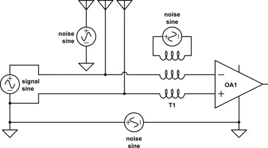
If the impedance on each input is equal (that is, the line is balanced), then any currents induced on the inputs from noise sources will also have equal voltages. Thus, they will appear as a common-mode signal (\$V_{CM}\$ above), allowing them to be rejected by the op-amp.
CMRR, according to defination is, tendency of Amplifier to reject the signal which is common on both inputs.
It's not an "average" of two signals but something which is common.
If a noise is present, it will be common on both inputs and hence will not get amplified. Hence it is desired to have high CMRR.
See this question for more details.