28

Let's say I wanted to make a widget containing a relay to switch between two antennas. There is a coax transmission line coming in from the transmitter, and two going out, each to a separate antenna. Inside is a relay which switches the center conductor, and the shields terminate into a metal enclosure around the relay:

schematic

simulate this circuit – Schematic created using CircuitLab

Let's further say that this is operating at HF, so the enclosure is very small relative to the minimum wavelength this device will encounter in operation.

At point A, there is an impedance discontinuity. The coax was \$50\Omega\$, but inside, it will be something else. At point B there's another discontinuity, as we transition back to \$50\Omega\$. So, there must be some wave reflection happening here.

What effect would this have on the transmitter? Would it result in a horrible SWR, or no? Why?

Phil Frost
  • 56,804
  • 17
  • 141
  • 262
  • It's more than you're asking for, but if you have some time on your hands: http://literature.agilent.com/litweb/pdf/5988-6505EN.pdf – The Photon Jun 13 '13 at 16:21

3 Answers3

28

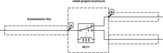
Probably very little effect at all as long as the dimensions are small. Coming from the left hand side, there will be a reflection from point 'A' followed closely by an (almost) equal and opposite refection from 'B'. As long as the distance from 'A' to 'B' is small, these reflections will effectively cancel-out.

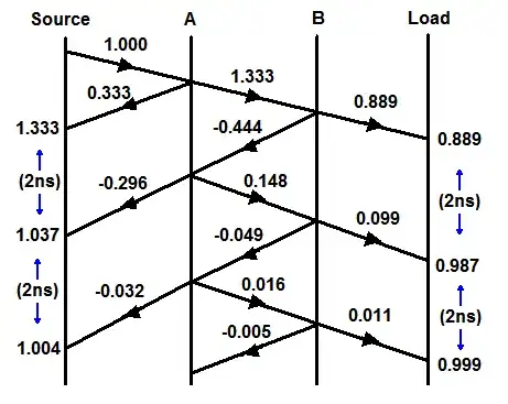
As an example, let's say the impedance inside the switch is 100Ω. The reflection coefficient at 'A' will be 0.333 and at 'B' it will be -0.333. If the enclosure width is say 200mm, the time between these reflections will be around 1ns (very small at HF).

Reflections will continue to 'bounce' between 'A' and 'B' and each time there will be some energy coupled into the transmission line but these will occur 2ns apart and will be attenuated each time due to internal losses.

We can draw a reflection diagram showing the effect of a unit step travelling down the line. The vertical axis represents time and the horizontal axis distance. With the example figures, there will be some overshoot at the transmitter lasting a few nanoseconds. Please excuse the amateurish diagram!

Reflection diagram

Edit :-

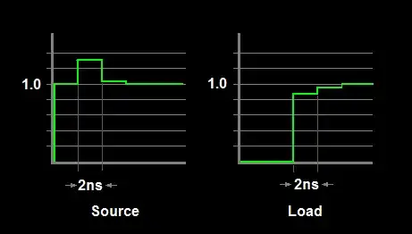
Following supercat's suggestion, I have added another sketch showing the resultant waveforms at the source and load. The step width is the round-trip time across the switch and back.

simulated scope traces

However, whilst this kind of diagram is useful to gain an insight into what is going-on, trying to calculate the actual overshoot amplitude is not too helpful. Effects such as finite rise and fall times, multiple reflections inside the switch ( eg, each side of the relay contact) and other effects will mostly smooth the theoretical transitions. I have not even addressed line attenuation and other losses, nor have I estimated the actual impedance of the relay switch which would be non-trivial. At best you can only estimate a worst-case scenario.

MikeJ-UK
  • 5,348
  • 15
  • 20
  • 2
    I've never seen this type of diagram, but it is by far the most intuitive explanation I've seen. Makes perfect sense now. – Phil Frost Jun 13 '13 at 15:09
  • Nice diagram. It might be helpful to also show a scope trace of the step response at A and B, and say that each "step" observed on the scope trace is the round trip time through the middle section. That would help make clear what is conditions would have to be met to avoid problems, in both the digital and analog domain (e.g. when sending a digital signal, what sort of slope would be necessary to avoid false transitions due to ringing). – supercat Jun 13 '13 at 15:16
  • Obviously those passive video cable splitter boxes work; it must be exactly the same principle. – Kaz Jun 13 '13 at 16:31
  • 2
    Perfect answer and diagram +1 – Andy aka Jun 13 '13 at 16:33
  • I'd upvote you again for the scope trace, but I can only upvote once. One thing that's nice with the diagram is that shows why it's important to keep the region with the "unusual" impedance short. Another thing I was just thinking might be worthwhile to add, if it wouldn't overcomplicate things too much, would be to show what happens if a line is only source-terminated or only load-terminated. – supercat Jun 14 '13 at 15:24
  • 1
    Normally, it won't matter too much if a line is terminated on both ends; if a line is load terminated, no signals should travel toward the source, so the fact that signals traveling that way would get reflected wouldn't matter. If a line is only source-terminated, signals hitting the load would get reflected, but they'd get harmlessly reabsorbed by the source. An mismatched area in the middle of the cable, though, can cause a lack of source termination to be problematical. – supercat Jun 14 '13 at 15:41
  • Cristal clear with the diagram and scope traces. +1 – Mister Mystère Nov 18 '15 at 11:10
1

Given the short connections, the effect will be negligible.

Leon Heller
  • 38,774
  • 2
  • 60
  • 96
1

The rule of thumb is that on a line shorter than 1/10th of signal wavelength, transmission line effects are so negligable they can safely be ignored. At HF, the wavelength would be 10-100meters, which again means if your wire is shorter than 1-10meters (depending on your exact used frequency), you can safely ignore the problem.

Imbrondir
  • 695
  • 4
  • 17