5

I'm considering learning to build air-core inductors for power applications.

For example, I presently want a .5-1 mH choke capable of handling 50 amps for two seconds. Winding my own air-core seems like it might be a cost-effective solution, but I'm not clear on how large coils like that would be physically constructed and held together.

I've used cable ties before, but that's a cheap and quick solution, not something I'd want to use for production, especially in any sort of high-vibration environment.

Is there a standard way such things are typically built?

Edit: these chokes are intended for use in ~600 VAC systems, so the insulation is going to have to have some pretty high withstand ratings.

Stephen Collings
  • 17,373
  • 17
  • 92
  • 180
  • 1
    Go to DigiKey or Mouser and get a air core rated for your size. Seriously though, 500 uH at 50 A is going to be a very large air core inductor. Why does it need to be air core? Ferrite would be much smaller. Also, if you want to produce these things in volume, get a company to do that which already knows how. You can do it yourself for one-off, but reinventing the wheel otherwise sounds a bit silly. – Olin Lathrop Jun 11 '13 at 12:55
  • Those distributors don't have what I want, or I wouldn't be asking! (Unless it's well-hidden.) We typically deal in low-volume stuff in 10-1000 kW. Many magnetics companies aren't interested at all. The few that are can take weeks to get a quote, more weeks to get prototypes, and the final cost is often higher than I'd like. We're optimizing for cost and time, not for physical size, so I'm looking for other ways. Winding our own choke may make sense in some cases. And while adding cores obviously makes things smaller, it adds an exotic part and makes construction more complex. Thus, air core. – Stephen Collings Jun 11 '13 at 13:01
  • I'm interested as well in why you consider not using ferrite material? It's likely to have a higher self-resonant frequency and lower losses with ferrite although care would need to be taken in choosing the best material and gapping it. – Andy aka Jun 11 '13 at 13:06
  • And when I say low-volume, I mean that fifty a year would be a high sales rate. Sometimes we just want three, EVER. The magnetics companies have to pay for their design time too, so the unit cost of each inductor goes up dramatically at those volumes. Being able to do our own one-off chokes quickly would be a great advantage. I'm also optimizing for design resources. To design and build inductors around cores, we as a company are going to have to learn a new and deep skill set, which probably won't pay for itself at our volumes. Air-cores are much simpler to design and construct. – Stephen Collings Jun 11 '13 at 13:11
  • What is your frequency range? If not too high, you can use heavy-gauge magnet wire, which holds its shape without a bobbin. From memory, car audio guys use big high-current chokes for passive subwoofer crossovers. Try an audio distributors like Parts Express. http://www.parts-express.com/pe/showdetl.cfm?partnumber=255-250 – markrages Jun 11 '13 at 15:40
  • Right now I'm targeting 4 kHz or so. – Stephen Collings Jun 11 '13 at 15:53
  • Audio distributors are an interesting idea! Do you have any idea about their voltage ratings, though? I expect they're not rated for hundreds of volts... – Stephen Collings Jun 11 '13 at 20:52

4 Answers4

3

It is as simple as using a form or armature over which you roll your wire. Once it's on the armature and wound up you can glue it together or even paint it with an epoxide paint that will give it strength. However, you will have to account for heat production. In some cases you might want to leave the coli on the the winding armature, if you've chosen the \$\mu_r\$ to be ~ =1 this could also be save.

If you are using litz wire you'll probably have to leave it on the armature.

There are companies that sell brackets and clips for this sort of thing. the term you will be looking for and here is a link to a page giving hardware. there are lots of competitors.

placeholder
  • 29,982
  • 10
  • 63
  • 110
3

These should be readily available; they are basic components in the hi-fi and professional (PA and recording) loudspeaker market.

50A is a bit above the average current rating but for short duration (2s) pulses at low duty cycle (you don't mention the duty cycle) the mean power will be relatively low.

A couple of well known suppliers : Wilmslow Audio and Solen the latter having quite a good datasheet.

Solen's 10AWG 0.68mh for example shows a DC resistance of 0.08 ohms, or 4V drop or 20W (edit: oops, 200W) dissipation at 50A. That would probably be unsustainable at 100% duty cycle - you can assess the results in your use case.

Doesn't look worthwhile to wind your own, to me.

  • The voltage ratings may be a problem. Solen lists a "test voltage" of 1000 VAC, which I assume to be a high-pot rating. I haven't seen any others that list a voltage rating at all. I didn't specify a voltage rating in my question; adding now. – Stephen Collings Jun 11 '13 at 21:00
  • 1
    Higher voltage ratings : what is the worry? presumably pulse voltage, across the inductance, without turn-turn insulation breakdown is what you are worried about : they may be able to provide a multi-section bobbin (it would effectively be several smaller inductors, in series, so that the voltage across each is within rating) I'm going to suggest contacting Solen with a more fully worked out specification - I believe they used to do custom winds for audio companies and they may still do so. –  Jun 11 '13 at 21:09
  • Solen was surprisingly helpful compared to most magnetics manufacturers! They gave me the datasheet on their wire (6kV insulation rating!) and offered to give me a cert. of compliance with each shipment. Very helpful! Thanks for the tip. – Stephen Collings Jul 10 '13 at 19:58
2

Here's a picture of how to wind an air-cored coil: -

enter image description here

I did some calculations based on 50 turns with a coil diameter of 10 inches and a solenoid length of 25 inches. Inductance came out at 219uH. I've assumed with a need to conduct 50A, each turn will repeat on a 0.5inch spacing.

Maybe you can make the spacing a bit smaller and get 500uH.

Is this size excessive for what you need? Only you can decide.

People do make coils this size when constructing Tesla coils to generate high voltage arcs/plasmas.

Maybe compare the size using a core: -

enter image description here

Is this better suited to your needs? Available in Farnell.

Andy aka
  • 434,556
  • 28
  • 351
  • 777
  • Thanks for that! One thing to keep in mind is that I only need two seconds, not continuous, so your wire gauge is probably much larger than necessary. Cutting that should greatly reduce the radius, which will further reduce the length. – Stephen Collings Jun 11 '13 at 15:18
  • Bigger radius means bigger inductance - look at the formula; it's R squared on top and only R below. If you can get the coil spacings down by half then you are at about 481uH. Inductance is all about area and the optimum area shape is a circle. Long and thin is not very good. More turns are good too. – Andy aka Jun 11 '13 at 16:28
  • Ah, so it does, my mistake. – Stephen Collings Jun 11 '13 at 16:41
1

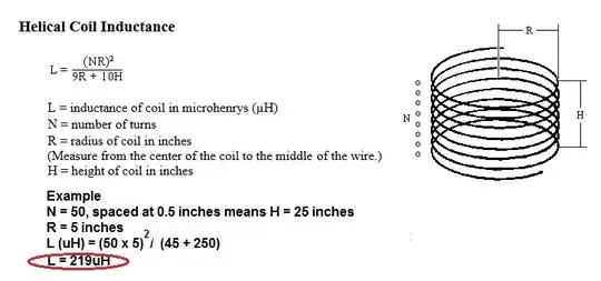
I've done this. Not for power conversion, but for PFNs. For single layer solenoids the easiest thing to do is get PVC pipe from the local building store. It comes in a variety of diameters, cut to length. Wrap magnet wire uniformly around and along the pipe. I see Andy gave you a formula. Here is another if you like metric.

L = \$\frac{9.8425 \text{ 10}^\text{-6} \text{ Dia}^2 \text{nt}^2}{4.5 \text{ Dia}+10 \text{ Len}}\$

where:

  • Dia = diameter (m)
  • nt = number of turns
  • Len = length (m)
  • L = inductance in Henries

Edit:

About winding. We used 14AWG magnet wire, wrapped on a ~8in by ~3ft PVC pipe. I no longer remember how much inductance this was, but it was milli-henries. Let's see, using the equation: it would have been for about 580 turns (14AWG is 14.9 tpi), and 375 meters of wire, would have been about 14mH.

As in Connor Wolf's comment, we drilled 2 holes (about 1/2 in apart) at each end of the pipe. The holes were chamfered to relax the bend radius, and not stress the wire there. To start at an end, put the wire through a hole away from the edge of the pipe, and back out the second hole nearer the edge. That fixed the wire for the start. Then just wind around the pipe keeping the new winding next to the previous, and keeping tension on the wire. Keep things a little tight as you go. The wire will form to the shape of the pipe. After winding to the other end of the pipe, cut the wire and thread it through the remaining two holes like at the start. We also placed a couple of strips of double sided tape along the length of the pipe, to help stabilize the wire while winding, but I don't think that was necessary.

It took three people to do this, kind of ad hoc. Two managed the pipe rotation and one to manage the wire and keep things aligned and tight enough. After the wire was in place it was very stable and didn't move, no varnish was needed.

We built some smaller inductors first for practice, like 4in diameter by 1ft length, using the same technique.

Edit: A couple of additional thoughts.

We didn't have easy access to a lathe. If you do, it could turn this from a tedious 3 person operation into a not so bad 1 person task. The lathe could be used to manage the pipe (spooler). Also, you could prep the pipe surface. A helical groove could be cut (threading the pipe) to give a channel to lay the wire into. Not a machinist, but based on experience having plastic milled, if you did thread the pipe you would probably want to:

  • use a sharp tool.
  • turn slowly to keep the PVC from getting hot.
  • control humidity to keep the static at bay.

Googling PVC turning yields this.

gsills
  • 7,133
  • 16
  • 22
  • How do you physically stabilize the magnet wire on the pipe? – Stephen Collings Jun 11 '13 at 18:46
  • @Remiel - Normally, stuff like that is wrapped onto the core (the pipe in this case), and then painted with lacquer, which basically glues it to the pipe. Any other non-conductive adhesive will probably also work (hot glue is easy, if not long-lasting). You can also drill holes through the pipe at the end of the coil, and feed the wire back through the holes to capture the ends. In your case, though, the wire is so heavy it'll probably stabilize itself. – Connor Wolf Jun 11 '13 at 22:09