7

Is it possible to build a motor driver using only a 2N2222 transistor?

If yes, then how?

Toby Jaffey
  • 28,796
  • 19
  • 96
  • 150
gomek
  • 465
  • 2
  • 7
  • 12

2 Answers2

18

Well, by motor driver... you could mean anything.

Is the motor AC or DC? Do you want to be able to vary the direction of the motor? How about the speed? What about braking the motor?

A 2N2222 is quite a powerful transistor, but is only good up to 800mA or so. So any motor you use must not consume more than this current when spinning and when stalled, or the transistor may burn. Also, the 2N2222 is rated for 40V maximum, so you can't drive high voltage motors.

Here is probably the simplest circuit:

+12V ---------+---------+
              |         |
             / \        |
             |M| motor ---  1N4001
             \ /       / \
              |         |
              +---------+
              |
            |/
CTL -/\/\/--|    2N2222 NPN
      1k    |\>
              |
             ---
              -

The 1N4001 is a flywheeling diode. As the motor is an inductor, when you turn it off the energy has to go somewhere. The diode provides a path for this; otherwise, the transistor could be burnt out by switching the output off.

This "driver" allows you to run the motor forwards and coast it. With PWM, you can vary the speed.

Here is a H-bridge using four 2N2222 transistors.

+12V --------+------------------------+
             |                        |
      1k    /  c                    c  \   1k
1 --/\/\/---|   2N2222        2N2222   |--/\/\/--- 3
            \> e                    e </
             |       +       -        |
             |-------- MOTOR ---------|
             |                        |
     1k     /  c                    c  \   1k
2 --/\/\/---|   2N2222        2N2222   |--/\/\/--- 4
            \> e                    e </
             |                        |
            ---                      ---
             -                        -

Making S1 = 1, S2 = 0, S3 = 0, S4 = 1 the motor would go forwards

Making S1 = 0, S2 = 1, S3 = 1, S4 = 0 the motor would go backwards

Making S1 = 0, S2 = 0, S3 = 0, S4 = 0 the motor coasts

Making S1 = 1, S2 = 0, S3 = 1, S4 = 0 the motor would brake (slow down quickly)

Making S1 = 0, S2 = 1, S3 = 0, S4 = 1 the motor would also brake

Making S1 = 1, S2 = 1 would be bad and should be avoided. It would cause both transistors to come on giving a direct path to ground. The transistors would burn up, and you could damage your power source. The same applies for S3 = 1, S4 = 1, as well as setting all switches on.

There should also be diodes across each transistor, anode to the emitter. For simplicity and due to the text-only media, I omitted these. Use the same 1N4001's.

You could also replace the 2N2222's with something else to allow it to drive heavier loads. With heavier loads it's a good idea to use heatsinks on each transistor.

The inputs can be controlled from an Arduino.

Thomas O
  • 31,546
  • 57
  • 182
  • 320
  • It's a DC motor. Change in direction is required and so is change in speed. Is that possible with the circuit you provided above? – gomek Nov 28 '10 at 11:23
  • To change the direction can I use just any PNP transistor or do I have to use specific ones? Also can I use this motor driver with an Arduino? – gomek Nov 28 '10 at 11:36
  • You don't need a PNP transistor, it just makes the circuit easier. – Connor Wolf Nov 28 '10 at 13:35
  • @gomek If you want to reverse the direction you can install the motor backwards. But if you want to be able to change the direction with your Arduino when you want, without removing the motor and installing it backwards, you can use a H-bridge. – Thomas O Nov 28 '10 at 13:37
  • @Fake Name, the circuit is designed for an NPN. Using a PNP would probably not work well. – Thomas O Nov 28 '10 at 13:38
  • @gomek You can use this with any device that can supply a few mA (<5mA) of current and at least 1 volt. That means Arduino, a PIC microcontroller, even a parallel port on your computer. You mustn't apply an input voltage higher than the power supply voltage though. – Thomas O Nov 28 '10 at 13:39
  • If you need higher power, I would step up to a darlington pair or a FET. The 2222 will probably not stand up to most motors stall current (the condition where the motor is running at full power and is stalled out) – mjcarroll Nov 28 '10 at 15:55
  • @Thomas O- Is it possible to build a H-bridge using only the 2N2222 transistors? Currently, I happen to have only these transistors at hand. – gomek Nov 28 '10 at 16:14
  • @gomek - See my edit for a schematic. – Thomas O Nov 28 '10 at 16:57
  • problem there -- you wouldn't be able to drive that H-bridge directly with logic levels. the low-side transistors (2 and 4) yes, but the high side transistors will have problems. To get the high side of the motor anywhere near the +12V rail, you'd have to have a control signal at least Vbe,sat (say 0.8V) above the 12V. Using logic directly on transistors 1 and 3, the high side of the motor will only be able to come up to about Vbe,sat BELOW the logic high level, perhaps about 4V at best. – JustJeff Nov 28 '10 at 17:18
  • @JustJeff Good point! To solve this you could use some open collector drivers with 1k pull ups. Or you could try replacing them with PNPs and grounding them (with pull-ups so they float to the supply rail.) – Thomas O Nov 28 '10 at 17:19
  • @ThomasO, BJTs do not have an issue with floating like FETs can. This is an important advantage when bread boarding as far as I am concerned. – Kortuk Nov 29 '10 at 02:27
  • Thanks. So does this work with the Arduino or not? – gomek Nov 29 '10 at 03:42
  • @Kortuk, yep, but you need to make sure they have a logic signal to switch off. PNPs switch on when they have no b-e current, so you need to make sure that b-e current is present. – Thomas O Nov 29 '10 at 11:17
  • @Gomek, it *should* work. You may need to find some PNPs and use the pull-up idea I mentioned. I'd recommend you buy an actual H-bridge IC though when you can - they're only a few bucks. – Thomas O Nov 29 '10 at 11:18
  • @ThomasO, NO, Both PNP and NPN need base emitter-current to get emitter-collector current. They both operate on taking base-emitter current and multiplying. I am not sure whom told you otherwise but they are very very wrong. If you leave either base floating they turn off. – Kortuk Nov 29 '10 at 13:33
  • @ThomasO, without base current it is two diodes. With base current you manage to trick current across the barrier of the reverse biased diode. – Kortuk Nov 29 '10 at 15:48
  • question- do I connect the switches (s1,s2....) to the Arduino inputs? – gomek Nov 29 '10 at 18:08
  • @gomek, yes, and don't forget the 1k resistors! – Thomas O Nov 29 '10 at 19:06
  • I built it but it doesn't seem to be working!! :( – gomek Nov 30 '10 at 07:58
  • Sorry for the mistake. The cicruit works fine. Thank you. – gomek Nov 30 '10 at 09:24
  • @gome, Glad to hear! enjoy. Then get a real h-bridge on your next components order, they are very useful. – Thomas O Nov 30 '10 at 14:56
1

Yes, it can be done very simply, but you don't get much power or position control.

schematic

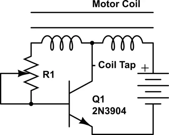
simulate this circuit – Schematic created using CircuitLab

The circuit uses the back-EMF from a single motor coil to drive the transistor, so that one transistor is all that is needed to turn the motor. Because of the back-EMF drive, it can work on different kinds of motors such as pendulums as shown in this patent, here is a also a good link.

Glorfindel
  • 1,245
  • 3
  • 15
  • 20
keantoken
  • 11
  • 2