4

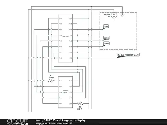
I have a serial to parallel chip ( 74HC595-N ) which works well when I run the arduino script made for it. ( the current wiring work perfectly when I send data through the data pin )

But then I started to play around with other pins, leaving the 74HC595 circuit simply not initialized, I have weird behaviours happening. (I don't use the PIN in the 2nd script, I use other pins ).

I realized that when I play around with my 2nd circuit, for no apparent reason, the lights from the first circuit change state.

I though : uhhm, must be that weird concept of "floating voltage" I heard about... Not sure how to address that, but fair enough.

So I decide to fix the problem the lazy way and unplug the 3 cables ( latch, clock and data), great the light stopped flashing... Oh wait now ALL the lights are permanently ON. Since I'm not sending anything through the data cable, I'd like the LED to be OFF by default. I've tried to put some resistors in a attempt to create a pull up and/or pull down resistance, but it changed nothing ( possibly because I don't know what I'm doing as I don't fully understand what's going on and the details of how that chip work)... I'm just impressed I didn't blow anything up.

I know you'll say it's probably a useless question and bla bla bla, but I'm still learning and most of the "project" I'm doing right now are useless anyway, so I'd like to understand why all the light are on, and how to fix this problem. Kind of a side quest in my electronic adventure.

I drew a diagram from CircuitLab. ( Ps.: I know I kind of wired the 7segments display a weird way, I just figured out how to count the PIN order recently ... did I told you I was beginning ? ) enter image description here

FMaz008
  • 553
  • 2
  • 6
  • 16
  • Your text needs to decide on a single part number... – Ignacio Vazquez-Abrams Jun 10 '13 at 21:08
  • @IgnacioVazquez-Abrams I'm having trouble with typing 595, I've fixed it. Thanks for pointing it out. – FMaz008 Jun 10 '13 at 21:11
  • If you are using a 74HC595, you are using a HCMOS part. by unplugging the three cables, you could have severely damaged your device because of (1) ESD, and also (2) both P- and N- MOSFETS could have been on. – fuzzyhair2 Jun 10 '13 at 21:15
  • @fuzzyhair2 Ok, well I didn't know. But I guess I'm lucky as the chip (both) are still working fine... even if I did that over and over today. – FMaz008 Jun 10 '13 at 21:21
  • Ok. yeah just be careful with CMOS stuff. Even though they have built-in ESD protection they could get damaged if you walk accross a carpet or somjething/. – fuzzyhair2 Jun 10 '13 at 21:22
  • @fuzzyhair2 I planed ahead, knowing I might do some pretty stupid things while learning: I bought 3 spare. So I should never boot/close/start my circuit with the 3 cables unplugged ? (Because everything was shutted down when I unplugged them) – FMaz008 Jun 10 '13 at 21:26
  • @FMaz008 Correct. See this document from Texas Instruments: http://www.ti.com/lit/an/scba004c/scba004c.pdf – fuzzyhair2 Jun 10 '13 at 22:46
  • Good question (actually not a useless question as you expected people to say). The community here can be really rough on newbies (especially if you don't phrase your question perfectly), but keep the good questions coming! – Nick Bolton Jul 21 '21 at 14:52

2 Answers2

5

The problem here seems to be that you're assuming that the outputs of the 74HC595 will all be low upon power-up.

This is not a valid assumption. The datasheet makes no guarantee about the state of the outputs upon power-up. They could be high, they could be low, they could vary from part to part, they even could be a mixture of high and low on different pins.

Basically, the only way to ensure that the 595's output pins are in a known state when you power it up is to have a circuit that triggers the MR input when the system is powered, and continues triggering the MR pin until the 5V power is stable.


As an aside, I actually was recently working on a project where I needed some additional outputs, and I specifically didn't use a 75HC595 for exactly this reason - you cannot guarantee it's power-on state.

Connor Wolf
  • 31,938
  • 6
  • 77
  • 137
  • Connor, what alternative did you use to the 595? – Bertus Kruger May 30 '14 at 20:04
  • @BertusKruger - A Microchip MCP23S08. It's a SPI-interfaced IO expander. Rather an odd duck of a chip, but it has internal power-on-reset electronics, and just needs a SPI interface. You have to set it up from your MCU though (this was fine in my application). – Connor Wolf May 30 '14 at 20:10
  • Nice little setup with I2C as well. Would the MCP23SO8 be able to be chained? – Bertus Kruger May 31 '14 at 21:00
  • @BertusKruger - Either version can have multiple devices on the same bus, with addressing. Either 4 devices (MCP23S08) or 8 devices (MCP2308). As usual, read the datasheet. – Connor Wolf May 31 '14 at 22:58
  • > "I specifically didn't use a 75HC595 for exactly this reason" Damn, I just ordered a bunch of 75HC595's (before discovering the undefined power-on state behavior). Maybe I'll get myself some MCP23S08's too. – Nick Bolton Jul 21 '21 at 14:55
3

I'd like to understand why all the light are on, and how to fix this problem

Put pull-down resistors on unused or open circuit inputs like clk, data and latch. Without anything connected to them they will float around to strange values and clock randomly any random voltage on the inputs and light LEDs randomly or consistently if the data input decides to drift high for a while. CMOS doesn't work well with open-circuited inputs.

To quote yourself: -

must be that weird concept of "floating voltage" I heard about... Not sure how to address that

Hopefully you do now - use 10k ohms on each open-circuit line to ground

Andy aka
  • 434,556
  • 28
  • 351
  • 777
  • Ok, so I did add 3x 10Kohm resistance, 1 for each cable that makes a link between the pin 11,12,14 and the Ground. Now the light doesn't flash anymore, but when I load my 2nd scenario, the last value is kept displayed ( as if the display was frozen ). If I unplug the 5V and plug it back, all LED will be on. – FMaz008 Jun 10 '13 at 21:35
  • You need to add a power monitor IC then, to keep ~MR low until power is stable and the clock rises. – Ignacio Vazquez-Abrams Jun 10 '13 at 21:48
  • @FMaz008 even though you took the power away, CMOS will take power from any input that is set high (maybe Latch or clk or data) and keep the device alive. You remove power and keep inputs "live" and you may damage your CMOS. – Andy aka Jun 10 '13 at 21:58
  • @Andyaka When I said I removed the 5V, it was from everything. ( no more power anywhere on the breadboard or arduino ). Latch, clock and data are pulled down now. So since the segment is common anode, it's sending LOW to all input and the LED goes ON. – FMaz008 Jun 10 '13 at 22:02
  • Did you have any power decoupling caps on the circuit containing the 595 - removing power would keep these charged up and quite possibly to a level where they retained the memory in the D type latches in the shift register. – Andy aka Jun 11 '13 at 07:33