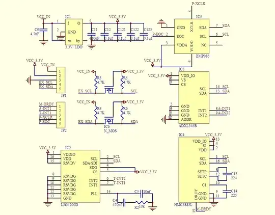
In the image above, could someone please tell me what the MOSFET is doing? From what I gather, it is there for switching between the VCC_in and the regulated voltage, in conjunction with the SDA and SCL lines. However, if all the components are receiving the regulated 3.3V from the voltage regulator (IC1) then why is the MOSFET needed? Is it if you were to be using a microcontroller which runs off 5V, and thus the SDA/SCL lines are also at 5V? Thus they need to be switched down to 3.3V?
I'm trying to recreate this design, but the input voltage is already regulated to 3.3V as the PIC I'm using is powered and needs 3.3V anyway. I've taken the regulator out I'm wondering if I can take the MOSFET out too.