7

I'm working on a dual headphone amplifier. I've discovered that it has a pretty bad turn-on transient that results in a loud pop if headphones are plugged into the amplifier when it is turned on. The split positive and negative rails rise very quickly at slightly different times due to the mechanical action of the DPDT latching switch, S1.

What is the best way to handle this? I figure something that could get V+ and V- to ramp up slowly and evenly at turn-on would solve the problem. Is there an elegant way to accomplish this?

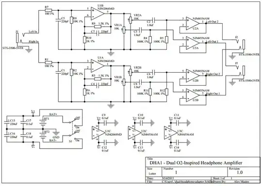
Here is the schematic. BT1 and BT2 are 9V batteries.

enter image description here

original circuit link here

Andy aka
  • 434,556
  • 28
  • 351
  • 777
strobot
  • 71
  • 3
  • I see from the very choice of op-amps that this is derived from ideas by "NWAvGuy". – Kaz Jun 07 '13 at 22:26
  • One idea is to use an analog switch (FET) to mute the output stages for some time when power is applied (perhaps determined by an RC constant, similar to a power-on-reset circuit). A FET switch will add some small amount of distortion, however. In a large power amp (that doesn't run on batteries), you might use a muting relay which is activated under various conditions: a DC fault is detected, excess current (output stage is shorted) or at startup. – Kaz Jun 07 '13 at 22:36
  • 1
    Use a relay to connect the headphones to the amp after say 5 seconds. This wouldn't work for battery operation, or at least not for long as it drains the batteries. – jippie Jun 07 '13 at 22:36
  • I think you've just got to try things because it's not a case of reading the op-amp specs and seeing the reason. Try shorting the inputs of the final stages to 0V instead of going thru those 100k's - does that make a difference - if so then it's up-stream with the NJM2068s - narrow it down strobot - prevention is better than cure! – Andy aka Jun 07 '13 at 22:42
  • Why do you have DC coupled inputs and outputs, but couplers before the output stage, haha. – Kaz Jun 07 '13 at 22:43
  • 1
    @Kaz - because of the crap bias currents causing DC changes with the pot changes? – Andy aka Jun 07 '13 at 22:44

1 Answers1

2

A very simple solution is to put some small amount of resistance or inductance in series with switch (both V+ and V-). All your 0.1uF caps will have a slightly slower RC charge curve and will dampen the transients. Of course you need to balance out the size of the resistor with the current and voltage requirements of your amplifiers. Inductance will choke the transient yet have lower DC resistance. Also ferrite beads can be used which would probably work the best if you pick one that won't be saturated by your inrush current.

Also don't leave your unused op-amps with their inputs floating. If conditions get just right they can oscillate and generate lots of noise.

user6972
  • 1,517
  • 9
  • 13
  • Why the downvote? Some form of series impedance with S1 will tame the transients and help reduce the pop to more of a small click. It's easy to try and you could simulate it too. The only other quick solution is more complicated. Add large RC which turns on a p channel JFET audio switch. This will float the output until the slow RC charges enough (after the amps have powered on) to enable the output. – user6972 Jun 11 '13 at 08:21
  • Of course I'm assuming that the OP's isolated his problem to S1's transients. The problem could be in U1B/U1A getting to their quiescent points...which output jfets would solve. Perhaps even just putting 2 in on U1A and U1B would be enough to stop the popping sound while leaving the buffers alone. – user6972 Jun 11 '13 at 08:32