7

I'm new to op amps and have tried many circuits but don't get the results I expect. I know I must do some math but I get so confused. I thought my question is really simple but it turns out it's not.

I just want to amplify an electret mic to 5V. Thus 2.5V bias with no input, then 0 and 5V as min and max for signal. Must I build this circuit and just change the values?

enter image description here

PeterJ
  • 17,131
  • 37
  • 56
  • 91
Roelf Daling
  • 113
  • 2
  • 2
  • 8
  • 1
    The output of a microphone is proportional to the loudness of the sound hitting the microphone. If you have too much amplification, even soft sounds will be distorted. If you don't have enough amplification soft sounds will appear too quiet. How loud is the maximum sound signal and how many milli-volts signal does the microphone produce when picking up that sound? Also, what are you going to connect the output of the op-amp amplifier to? It won't drive a speaker but it might drive hi-impedance headphones OK. – Andy aka Jun 02 '13 at 12:06
  • 1
    That circuit will probably do what you want as it stands; though as Andy says it depends on the sound level you have. And on how well the opamp drives close to its supply rails. You may only get 1V and 4V for example unless you choose an opamp with "rail to rail" output drive. –  Jun 02 '13 at 12:14
  • Hi, I want room amplify normal voice from about 5-10 cm away from the mic, read that it outputs about 20mv. I know how to set amplification to 100.but can get the 2.5 bias right. I'm not driving g any speaker I'm just using the signal for modulation. – Roelf Daling Jun 02 '13 at 12:25
  • If you have a 5V supply, 2.5V is simply half of that; the divider (2x 10k resistors shown) is OK as-is. I would decouple that point (2.5V) with 1uf to ground, that ought to reduce noise a little. –  Jun 02 '13 at 12:30
  • I build this with a lm324 and it doesn't work at all. Now looking at the first circuit posted in the first answer of this question http://electronics.stackexchange.com/questions/57824/how-do-i-get-5v-for-loud-noise-0v-for-silence-from-electret-microphone-or-oth. But I don't understand what is suppose to go in at VCC2? – Roelf Daling Jun 02 '13 at 14:02

4 Answers4

4

Actually the circuit you have after a few tweaks would be pretty good, although I didn't look up the particular opamp to see if it is appropriate for this use.

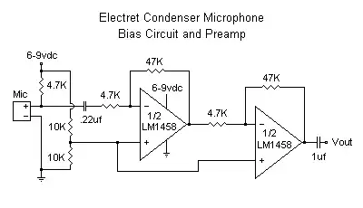
The first change I'd make is to put a cap to ground on the + input line to the opamps. Since the impedance is 5 kΩ, 1 µF would give you a rolloff of 32 Hz, which is fine since we're only trying to keep power supply noise from feeding into the amplifier.

The 220 nF input capacitor should be a bit higher. As it is now, it will form a low pass filter with the 4.7 kΩ resistor in series with it with a rolloff of 155 Hz. That's a bit skimpy, although perhaps your mic can't support frequencies lower than that. Still, I'd make it at least twice what it is, but more likely use a 1 uF cap. However, make sure not to use barium titanate or related ceramics because those exhibit microphonics. Just putting two of the caps you already have in parallel could be good enough.

Your voltage gain is only 100. You probably want more to make 5 Vpp from a electret mic. With this gain, you need 50 mVpp from the mic, which sounds a bit high. Maybe you're fine as is if you will be using a high enough resolution A/D so that the signal can only use part of the range most of the time, but you want overhead in reserve for short but loud sounds.

The 1 uF output cap allows you to float Vout at any level you want. Since you want 2.5 V, float it at that. A simple way to do that is to connect it to a voltage divider from the 5 V supply. Two 100 kΩ resistors would do that nicely.

Olin Lathrop
  • 310,974
  • 36
  • 428
  • 915
  • Olin,where to put 100k dividers(O/P terminal of OPAMP or after the cap) – yogece Jun 02 '13 at 14:22
  • Hi, I build this with a lm324 and it didn't work at all. Thanks for your answer, once I get the right op amp I will add these things to my circuit. – Roelf Daling Jun 02 '13 at 14:35
  • @yogece: After the cap. – Olin Lathrop Jun 02 '13 at 14:44
  • @RoelfDaling - The LM324 is really not a very good op-amp. The output cannot swing very high (only to within ~2V of the positive rail). The key-word here is **rail-rail** op-amp. You need a part that has rail-rail output swing. – Connor Wolf Jun 03 '13 at 16:42
  • Doesn't the circuit needs a decoupling capacitor between the two op-amp stages? Wouldn't the seconds op-amp also amplify the offset of the first one? – m.Alin Jun 09 '13 at 09:47
  • @m.Alin: Yes, good point. At a gain of only 100 I didn't consider that. But I just checked and the LM1458 has a large offset, up to 5 mV. The offset is eventually eliminated by the output cap, but excessive offset can cause clipping to one rail internally. A 1 uF cap in series with the output of the first amp would be a good idea. Make sure to use a ceramic that is not susceptible to microphonics. – Olin Lathrop Jun 09 '13 at 14:01
2

The electret microphone works on the basis of a variable capacitor formed by a very thin sheet of polarized insulator that moves with sound pressure. The changing voltage produced is buffered by an internal FET so that it requires an external power supply to allow it to operate. That's why you have to add an external resistor. enter image description here

The size of the external resistor and the voltage it is being fed from will determine the current through the FET and its size will determine the change of output voltage for a change in current. Too small a value will reduce the output. Usually a mA or so is a reasonable current. Your 4K7 is a reasonable choice but you could always try a 10K to give more output.

The electret needs to be decoupled (DC split from the AC) which you have done with the 0.22 uF capacitor. I'd try to avoid using a cheap disc ceramic here. You'd be surprised how good (or bad) a microphone they can be. You might also want to add a capacitor across the bottom 10k resistor of your potential divider (say 10uF) as any variation (noise) in voltage at this point will be amplified along with the output from the mic. Your two stage (x10) ---- (x10) is a good idea as it will produce a better bandwidth than a single (x100) amp.

JIm Dearden
  • 18,926
  • 30
  • 40
0

Consider this schematic below.

schematic

simulate this circuit – Schematic created using CircuitLab

  1. At steady state, electret mic has resistant about 1K ohm gave us 0.4545 volt with 10K pull-up.
  2. Op-amp in this configulation work as inverting amplifier with 2.5V as virtual ground. The inverting input will has same voltage as the non-inverting which equals to 2.5V
  3. At steady state, the coupling will charge-up and make coupled input oscilate around 2.5V of inverting input.
  4. The gain of this citcuit equals to -R5/R4.
M lab
  • 1,191
  • 6
  • 21
  • The datasheet for the antique LM1458 shows that its minimum supply is 10V when it barely works. It is not made to be a mic preamp since its noise is too high and its poor slew rate cuts high audio frequencies. The TL081 has a minimum supply of 7V or 10V on its datasheet. Its input bias voltage is too low shown here. The max gain of 10 in the circuit shown here is too low for it to be a mic preamp. Most electret mics need a minimum of 2V on them and draw a max current of 0.5mA then the 10k feeding it from 5V will not work. – Audioguru Nov 08 '21 at 22:31
  • Thank for useful comment, I made this circuit using tl071 and It work quit well. – M lab Nov 09 '21 at 01:05
0

If you are driving a modulator (eg FM or AM radio) I'd consider changing the 1st stage of your amp to incorporate AGC (automatic gain control) to prevent over-modulation and still be able to decently modulate quiet sounds: -

enter image description here

Here is where I found it - scroll down past the advert.

It seems a fairly straightforward design and is designed for a modulator. Insert this in place of the 1st op-amp in your circuit; R1 on this circuit connects after the 0.22uF on your circuit. The "output" on this circuit connects into the 2nd 4k7 on your circuit. You may also consider reducing the gain of your 2nd op-amp in case the circuit above overdrives your 2nd op-amp into distortion.

Here is also a link to another mic agc amp and FM modulator

Andy aka
  • 434,556
  • 28
  • 351
  • 777
  • Good suggestion about adding agc but the mic shown is not an electret type. Simple mod is to add a decoupling capacitor between mic and input resistor and a pull up resistor (5k) to power mic/match impedance. – JIm Dearden Jun 02 '13 at 13:20
  • @JImDearden if the OP follows my instructions in the paragraph between the links above all will be fine; "R1 on this circuit etc...." – Andy aka Jun 02 '13 at 13:29
  • 1
    You are quite right - I must learn to read. – JIm Dearden Jun 02 '13 at 13:30