20

Whenever I turn on my desk lamp, my board crashes. Sometimes I get garbage out of the serial port, sometimes it resets.

I tried adding some extra bypass capacitors on my breadboard, but that made no difference.

(My desk lamp uses a 20W, 12V halogen bulb. It has a transformer in the base)

Can anyone offer suggestions as to why this might happen and how I can stop it?

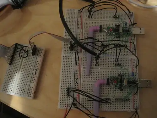
Here are two of the boards - they were USB dongles, but are both now powered from a single wall-wart via a 3.3V voltage regulator.

Watching on a scope, when I flick the light switch I see a spike on both 3V3 and wall wart lines.

Edit:

Here are traces of the input and output of the 3V3 regulator when turning the light on and off respectively.

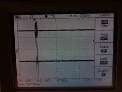
5V is on the top, 3V3 on the bottom

The regulator is a ZSR330.

Edit:

Some careful reading of the datasheet threw this up:

The RESET_N pin is sensitive to noise and can cause unintended reset of the chip. For a long reset line add an external RC filter with values 1 nF and 2.7 kΩ close to the RESET_N pin.

My programming cable connects a long wire via a breadboard to the reset pin. I suspect that this was the problem.

Toby Jaffey
  • 28,796
  • 19
  • 96
  • 150
  • 4
    You bring the most interesting questions Joby. This can be a very common occurrence, but most people are not able to reproduce it so well. – Kortuk Nov 23 '10 at 22:32
  • How far apart are the board and the lamp ?? and does the voltage fluctuation change if the lamp is further away from it ? – Zaxx Nov 24 '10 at 00:19
  • @Zaxx They were 1ft away, I've just tried 3ft and seen no voltage difference on the scope spikes – Toby Jaffey Nov 24 '10 at 00:27
  • 1
    @Joby Taffey how hard is it to move it further away from the lamp? Also can you hook one or the other up to a different outlet, preferably one on a different circuit? This might tell you a bit more about what is going on. – Kellenjb Nov 24 '10 at 02:46
  • and just connect a 10K load resistor to the output of the regulator and check whats the results. and whats the capacitance you have used for the filter capacitor ??? hope its at least 1000mico at the power supply end. – Zaxx Nov 24 '10 at 04:34
  • @Joby - do you get the same noise if you use the switch on the lamp, or the switch on the wall? The noise looks fairly wideband, I'm wondering if it is arcing in the contacts, being made worse by the inductance in the transformer. – Cybergibbons Nov 24 '10 at 07:17
  • @Joby - CC1110 is a popular chip, but I think we should steer away from creating new tags for a single part number, that could get out of hand really fast. Plus, it wasn't even the problem, but you didn't know that when you asked. I'll let you decide whether you want to delete the tag entirely, or replace it with [wireless], which is a used tag which seems to convey the meaning you want. – Kevin Vermeer Jan 28 '11 at 19:01
  • @reemrevnivek you're right, done. – Toby Jaffey Jan 28 '11 at 20:21
  • @Joby: What did you use for your omega symbol? It shows up as a square on my iPhone safari. – BG100 Jan 28 '11 at 20:41
  • @BG100 - It shows up as a square for me as well, tested on FF 3.6, Opera 11, on a Windows XP machine. Therefore, I'm going to replace it with the [HTML entity](http://meta.electronics.stackexchange.com/questions/136/138#138) `Ω`, which should render properly everywhere (unlike whatever Unicode symbol was used for the original copied from the datasheet). Unfortunately, this will push this question into 'Community wiki' status. – Kevin Vermeer Jan 28 '11 at 21:33

6 Answers6

13

The transient is getting through the regulated supply.

Try adding an inductor to the power supply positive output.

That may suppress the positive-going transient.

Tim Williscroft
  • 1,702
  • 11
  • 11
  • 3
    What value would you use? – Kellenjb Nov 23 '10 at 22:32
  • 1
    This is a conducted emission, but how to isolate it is nasty. – Kortuk Nov 23 '10 at 22:32
  • Why would that help? – Toby Jaffey Nov 23 '10 at 22:56
  • 7
    I think the speculation is that it's a current spike causing the problem. Inductors resist rapid changes in current, like caps resist changes in voltage. – pingswept Nov 24 '10 at 01:06
  • 2
    You've already got some capacitance, so adding an inductor turns into a better low-pass filter. – Tim Williscroft Nov 24 '10 at 01:09
  • @Tim Williscroft What value of inductor are you thinking? – Kellenjb Nov 24 '10 at 02:43
  • 2
    I can't tell the capabilities of that scope but if it can FFT the 5V line you should be able to tell at what frequencies your noise exists. Choose your LC filter corner frequency based on that. – Mark Nov 24 '10 at 19:27
  • 1
    Additionally I would add a reverse current protection diode around the LDO. Based on the appearance of the traces at this scale it looks like there are some instances where the input to the regulator is spiking lower than the regulator output. Without a path for this current to flow it will travel back into the LDO and depending on the LDO design it could screw with its operation quite a bit. This actually could be causing some of the ringing. – Mark Nov 24 '10 at 19:31
7

Is that mains circuit overloaded?

Halogen bulbs draw a large amount of current when they are cold, like 10+ times their normal current draw. This should only last for a split second, just long enough to heat the filament up to operational temperatures. Halogen bulbs do run very hot so perhaps this affect last longer / draws more current than your average incandescent, i'm not sure.

I would say that current spike is causing some issues on your mains lines.

Did you scope the input to the 3.3V regulator?

Mark
  • 11,627
  • 1
  • 31
  • 38
  • This is a good point - check the mains voltage. If necessary, probe it through an isolation transformer, like a cheap wall wart. (Don't plug your scope straight into mains because you could get all sorts of horrible transients destroying your scope - a 12V xformer will at least divide by 10 or 20 any transient.) – Thomas O Nov 24 '10 at 00:17
  • @Mark Yes, that wall socket is overloaded, I also have a 1500W electric heater on it. I tried unplugging everything but the lamp, it didn't seem to help – Toby Jaffey Nov 24 '10 at 00:25
  • @joby Those scope images make it look like the the LDO is oscillating, that parts claims no external components needed for stability but you may try some more decoupling on the input and output of the regulator. Can you make similar measurements at the input to the regulator and post them? – Mark Nov 24 '10 at 01:32
  • @Mark In the photos, the top trace is the input to the regulator, the bottom is the output – Toby Jaffey Nov 24 '10 at 09:40
  • Mark - these little 20W halogens aren't normally that bad, mainly due to the transformer limiting the inrush current significantly. Mains voltage halogens can be very bad. – Cybergibbons Nov 24 '10 at 11:03
  • @cybergibbons Well, its obviously going something nasty to the mains line, as if that 5V trace is the output from the wall wart then those transients are coming from the mains line. – Mark Nov 24 '10 at 19:13
  • @joby Are you sure thats a halogen bulb and not compact florescent? I would think that type of noise would be more indicative of a cheaply designed inductive ballast for fluorescents. – Mark Nov 24 '10 at 19:19
  • @Mark It's a small bulb, it runs very hot – Toby Jaffey Nov 24 '10 at 19:28
4

I had a similar issue with my powerline ethernet network adapters. When communicating they would induce up to 200mVp-p noise on the 3.3V line of my breadboard. It didn't cause any problems, because my MCU was rated from 3V to 3.6V, but it was interfering with my ability to scope the system. I never really sorted out the problem until I moved the adapter to another plug extension. This might have provided sufficient isolation between the power supply I was using (old computer ATX), or it could have been something else.

Thomas O
  • 31,546
  • 57
  • 182
  • 320
3

I see ground loop and may be you have lots of power, signal loops. effectively you have large area of single turn inductances. This loops work like secondary coils of air transformer (magnet antenna) which reacts to AC magnetic fields.

The midpoints of loops where you have joints are some center-points of this coils and produce variety of signals with very low source impedance and short circuit currents up to milliamperes, which make voltage of noise signals that high.

To fix it, try to rewire all inter-board symmetrically with single "grounding tree" and power, signals coming over twisted pair wires.

2

If I was going to power USB dongles directly from a PSU, it would be a 5V one, not a 3V3 one, because USB VBus power is 5V not 3V3. Not sure if that's the problem, but if they're incredibly marginal on supply voltage, that wouldn't help.

But probably your problems are just the kind of craptastic grounding you get on breadboard - your supply rails probably form a vast weak loop, just waiting to have problematic voltages induced on it.

You don't say where your bypass caps were added, nor their value, but you should make sure that you have plenty of capacitance right at the point the supply is used, not the far end of 6" of cable from the load. You will probably struggle to measure induced spikes sensibly with a scope, because so much will be picked-up on the scope's ground lead, but if you're going to try, then make sure you measure with both the ground-lead and the probe at the load, not somewhere else in the circuit.

  • Re: the 5V suggestion - There are two chips on the board, one has an internal 3.3V regulator and supplies power to the second - a CC1110. I am trying to power this chip directly (more detail http://blog.hodgepig.org/2010/11/23/im-me-dongle-uart/) – Toby Jaffey Nov 23 '10 at 23:00
  • @JobyTaffey, When I have worked with the CC1100 if you do not have excellent decoupling they throw a fit, but that probably has something to do with your question. – Kortuk Nov 24 '10 at 20:49
2

This doesn't apply to you, but maybe someone searching will find this: Semiconductors are light sensitive. If you have a precision analog circuit, and parts of it are in translucent cases, like glass diodes or metal-can op-amps (the bottom seal is translucent), you can expect significant offset shifts when light shines on the circuit. Modern black epoxy packages are less susceptible. It's easy enough to check if this is causing the problem: If the problem stops when the circuit is covered by a box or something, the problem is the light, not the EMI.

markrages
  • 19,905
  • 7
  • 59
  • 96