16

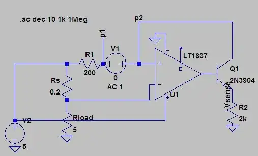
In the Linear Technology AN 105 on current sensing one can find the following circuit.

I am wondering what the purpose of the 200 ohm resistor on the inverting input is. It appears to have no effect.

enter image description here

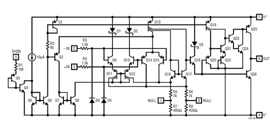
Note that in the following paragraph a virtually identical circuit is presented that is lacking said resistor:

enter image description here


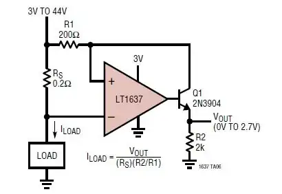
As a side issue: is there any downside to sizing the 200 ohm input impedance resistors significantly larger, e.g. 10k? (Keeping gain constant.) The aim would be to reduce the current the opamp draws from its supply to drive the BJT.


Edit 1: Need for Q1

In the comments it was questioned whether the output transistor Q1 was needed. See my comment below on my interpretation.

enter image description here


Edit 2: Johnson noise

enter image description here enter image description here

The Photon's back of the envelope calculation suggests that the input resistor's Johnson noise is not likely to be an issue even for large values if 0.1% (of output range) noise on the output is acceptable: $$ Vrms = 10\times \sqrt{R}\sqrt{\Delta f} \times 10^{-9}\text{in Volt}$$

For Vrms = 0.005V and 70kHz: $$ R = (\frac{Vrms}{1.3\times\sqrt{\Delta f}}\times 10^9 )^2 = 211 G\Omega $$

Max
  • 193
  • 6
  • It is a strange addition considering that "the same" circuit is shown without the 200R resistor when operating as a current measuring device up to supply voltages of 44V. Maybe you show the two side by side so folk don't assume it's something to do with bias currents. – Andy aka May 27 '13 at 17:35
  • @Andyaka Thanks for the suggestion. This makes thing indeed clearer. – Max May 27 '13 at 17:47
  • Yes there is a down side to upping the 200 ohms to 10k - the circuit will almost certainly oscillate because you've added gain. Currently the BJT's collector resistor means that it attenuates the op-amp output by 10:1 - this means happy-stability. As collector resistor goes above 2kohm Q1's gain rises above unity and may be on the brink of causing the LT1637 to go unstable due to the feedback to +Vin (negative feedback due to collector inversion) - no higher than 2k but, you can make R2 bigger (say) 20k and use a 2k for R1. Bottom line - I've never used it so I'm a little unsure. – Andy aka May 27 '13 at 18:02
  • @Kaz How do you get Vout=0.2 ohm x Iload? I get $$ V_{out}=I_{load}\times\frac{R_s\times R_2}{R_1}$$ For the given values that gives the claimed factor of 2 ohm. – Max May 27 '13 at 19:30
  • @Kaz Your question regarding the need for the transistor had me stumped. Though I think I know why it is needed: With the transistor, the current driving R2 is sourced through R1 thus depressing the voltage on the amplifier input. - If no external transistor was used, the current to drive R2 would be sourced from the op amp supply through Q25. What do you think? – Max May 27 '13 at 20:11

1 Answers1

10

The 200 Ohm resistor on the inverting input has no effect for an ideal op amp, which has no input current.

But real op-amps require a (very small) bias current, and also have offset currents flowing from the non-inverting input to the inverting input.

Because of the offset current it's best practice in a precision circuit to have equal impedances feeding the two inputs of the op-amp.

In the case of the LT1637 with 5 V supply, the offset current could be as high as 15 nA. If the input impedances weren't balanced this could cause an error of up to 3 uV, corresponding to an error in the current measurement of 15 uA.

is there any downside to sizing the 200 ohm resistors as e.g. 10k?

There's no real issue with a small change in that resistor value (for example to 211 Ohms or something), but no advantage either.

If you were to increase the R1 resistance to 10 kOhms, I'd start to worry about Johnson noise generated by the resistor. But I haven't looked at the effects carefully, and of course the maximum acceptable noise depends on your system-level requirements.

The Photon
  • 126,425
  • 3
  • 159
  • 304
  • Thank you. The offset current issue is something I was not aware of. I am still somewhat confused since as Andy aka pointed out, a circuit presented immediately after this one is lacking the second input resistor. - Though that may simply be an oversight. – Max May 27 '13 at 17:50
  • You can also look at the offset current as just difference between the two bias currents. I think the second circuit is just designed for cases where a few uA of error aren't important...but maybe there's something I'm not considering so I won't add that to my answer yet. – The Photon May 27 '13 at 17:53
  • I'm not convinced it's an input current balance thing but i'm struggling to see it as anything else - there's a near-identical circuit on the same link that doesn't use it and it purports a supply voltage range from 3V to 44V. Ditto if you look at the device data sheet as opposed to the app note. – Andy aka May 27 '13 at 17:56
  • @Andyaka, notice the first circuit runs the op-amp on the same supply as the load. The second circuit is to advertise the "over-the-top" input capability of the op-amp --- they may simply not have been designing for the same accuracy in that case. – The Photon May 27 '13 at 17:58
  • @ThePhoton I hear what you say but there's something bugging me that I can't put my finger on!!! – Andy aka May 27 '13 at 18:08
  • Regarding the Johnson noise issue: What would be the relevant bandwidth for calculating the thermal noise? My feeling is that it should be between 100 kHz or 200kHz as A >> 1 in this region and thus the thermal noise is not attenuated. This would give about 2µV RMS of thermal noise corresponding to 10 µA RMS current sense noise? - Am I on the right track with this? – Max May 27 '13 at 19:42
  • @Max,to get an answer quickly, I'd set up a simulation in LTSpice, adding an ac source in series with the resistor, and running an ac simulation to find what frequencies does the noise pass through. Also consider what is the bandwidth of the downstream circuit. – The Photon May 27 '13 at 19:46
  • @ThePhoton I ran the suggested simulation (see edited OP). Now on how to interpret the results. Should I do the following to get the noise in the Vsense? $$ \text{RMS noise of }Vsense = \int^{\infty}_{0}0.13\sqrt{R}\sqrt{f} df\text{ (in nV)}$$ – Max May 27 '13 at 20:41
  • I don't know your formula but it might be correct---just add an additional factor for the circuit response (from your simulation) inside the integral. Or for back-of-the-envelope purposes, just take sqrt(70 kHz) times the Johnson noise (in nV / rtHz). – The Photon May 27 '13 at 20:51