6

I need to buffer an input signal such that I do not load down the source, which is a 100k resistor. However, I need to buffer at least 6 channels, and for more advanced models I'd like to move to 10 channels (for the more advanced one I'd be okay using multiple chips though.)

I'd rather not use op-amps, because they will take up considerable space - just wiring the inverting or noninverting to the output, for example, uses a lot of space for traces - also, half the pins would be unneeded.

I'm not sure what chip or type of chip to be looking for - all the buffers I've found so far only work for digital logic, not analog signals. The buffer should have very low input bias current (nanoamps to hundreds of picoamps), like a JFET op-amp.

Thomas O
  • 31,546
  • 57
  • 182
  • 320
  • With less current then the MCU, as small as a voltage divider, and unity gain, faster then a bullet going the speed limit, it is "super buffer". Thomas, please remember the reason they pay engineers so well is that we are able to take a problem and find solutions that meet criteria, sometimes you need to make a product larger, go to 4 layers, and/or mount components on both sides of the board. – Kortuk Nov 22 '10 at 15:48
  • @Kortuk 4 layers is twice the cost. I'm still learning. If I don't know where to start, how am I supposed to learn? I do not need high speed. I am not requiring it to be as small as a voltage divider - I did not mention any of these. I said it should be small, but I did not specify a lower bound. I was looking for a chip which would basically be six op-amps configured as buffers. – Thomas O Nov 22 '10 at 17:23
  • @ThomasO, There are chips like that, if you had just said that someone would have found it for you. I am trying to give you feedback and help you laugh a little. – Kortuk Nov 22 '10 at 17:33
  • 3
    @ThomasO, if you want to sell a product please remember that FCC validation is hell to pay with a board that is 2 layer and has higher speed signals. Also remember that your signal speed is determined by your slew rate, not by the clock rate which is normally much lower. – Kortuk Nov 22 '10 at 17:53
  • @Kortuk, the product will be open source and I am not going to do FCC validation as it is very rare in the hobbyist market - given I am selling only 50-100 it's not worth it. – Thomas O Nov 22 '10 at 18:22
  • @ThomasO, I have added an answer with a buffer chip. I hope it helps. I do not know what the liability is in your case, I am not legal advice, but I always design with the FCC in mind. – Kortuk Nov 22 '10 at 19:32
  • 1
    are these signals going to an ADC? If So a simple unity gain buffer is not the proper solution to preprocessing a signal intended for an ADC. At least not if your after resolution greater than maybe 7 or 8 bits. – Mark Nov 22 '10 at 20:29
  • @Thomas O as a future engineer, you probably don't want to take the chance of getting government agencies mad at you. Although 50-100 is small there is still the possibility of getting caught if it does break regulations. Is it really worth potentially large fines and even possibly ruining your career just for a small project. Talk with a lawyer and make sure you have yourself covered before bringing anything to market. – Kellenjb Nov 22 '10 at 21:39
  • 1
    @kellenjb, I understand the risk I am taking. I live in Europe (UK), so CE is really the only thing that could come after me. But then how do things like magazines (say Silicon Chip magazine) get away with it...? Surely not all their projects are FCC certified, that's at least $5k each? IIRC, there is an exception for hobbyist things, I need to check it out. – Thomas O Nov 22 '10 at 21:48
  • @thomas o it doesn't matter where you live, it matters where you sell to. The EU actually has very strict regulations. Is it considered a hobby if you are marketing and selling it? – Kellenjb Nov 22 '10 at 21:54
  • @Kellenjb, I don't know. I plan to sell assembled versions, but these are kits - parts of a larger subsystem - a model plane. I have a previous question on this stuff - perhaps you should check that or post there. – Thomas O Nov 22 '10 at 22:42
  • @Thomas O the answers on your previous question seem pretty full, which is why I am confused why you aren't testing. Why even ask the question if you weren't going to follow the answer. My comment about the hobby was supposed to be a rhetorical question. – Kellenjb Nov 22 '10 at 22:58
  • 1
    depends on who you market and sell to actually. You don't need FCC certification to sell development kits, parts, modules. That is parts that are not intended for sale to or use by the general public. You are always bound by FCC rules to not knowingly exceed emissions limits (thats on the user's head), however you don't have to get your product certified until you market it or sell it as a contained device to the general public. This is why you'll almost never see FCC stamps on dev boards, i've had a few that i know would not have passed (PICDEM.net 2 for instance) – Mark Nov 22 '10 at 23:05
  • Thats not universal for all devices however. If your interfacing with some public systems that malfunctioning of your device could effect, you may need certification, but those devices don't generally fall in the 'incidental radiator' category we're talking about here. – Mark Nov 22 '10 at 23:06
  • @kellenjb: I will follow the advice as well as my own gut feeling. – Thomas O Nov 22 '10 at 23:10
  • @kellenjb: I don't know if you know how much it costs to get FCC/CE testing, but here it's about £5,000-10,000. That's about what I'd earn in 10 years with my current income. – Thomas O Nov 22 '10 at 23:11
  • 1
    How much it costs depends on the device and category it falls into. In both cases if its a "low risk" device you can get by with a Certification of Conformance. Basically you say to FCC/CE "I've tested it, its ok" you just better be able to provide test data if they come asking for it. If its a higher risk device, they will require testing by a known good lab, which is where the higher costs come in. – Mark Nov 22 '10 at 23:20
  • 1
    @Mark these are good answers for http://electronics.stackexchange.com/questions/5556/is-fcc-testing-necessary-for-all-devices – Kellenjb Nov 22 '10 at 23:22
  • 1
    You are tip-toeing a very narrow line with all this, everything i've heard of this product so far would indicate it does need certification. The line between "dev tool not for public use" and "fully commercial device" is pretty blurred. For instance all the Ardunio's i've see are FCC/CE stamped. They would have a hard time arguing in court that they didn't intend the product for the general public when their main selling point is bringing microcontrollers to everyone. If your intent is a plug and play device, you'd have just as hard a time arguing its not a full commercial product. – Mark Nov 22 '10 at 23:23
  • @Mark, it is not aimed at the general public. It requires considerable set up and configuration to work properly. It requires you to solder wires to it, and wire in your own battery. It's a dev tool of the Super OSD firmware, I suppose. If I could afford it, I would do so, but I can't. Either way, this isn't very relevant to the original question. – Thomas O Nov 22 '10 at 23:30
  • 1
    @Thomas O Can you address my question about why you asked http://electronics.stackexchange.com/questions/5556/is-fcc-testing-necessary-for-all-devices if you weren't going to follow the advice? If you found something out that caused you to not follow the answers it is acceptable, even encouraged, to post it as an answer to your own question. – Kellenjb Nov 22 '10 at 23:36
  • @kellenjb, the advice was mixed (esp. the Q linked by Kortuk), and it put me off, due to the high cost. – Thomas O Nov 22 '10 at 23:54
  • 1
    @Thomas O 1. I am not seeing what is mixed about the answers. Am I missing something? 2. So you are willing to admit that you might be regulations because you don't want to deal with cost? Engineering is still a field that very much respects ethics. You wont get far if you don't. – Kellenjb Nov 22 '10 at 23:59
  • @kellenjb, I simply can't afford it. There is no way for me to cough up £5k-£10k to get my product FCC/CE tested, so I will have to risk it - like every other hobby OSD I've seen. I do like to keep professional standards. I'm fairly sure it would pass FCC/CE, but as I said, I can't verify it. It will be flying up in the clouds, in the sky, so the only thing it could interfere with would be the plane itself, if it operates on 27 MHz or so. – Thomas O Nov 23 '10 at 14:10
  • If the board runs at 27Mhz then your trouble frequencies for FCC are more likely around 175Mhz-300Mhz which is a fairly well populated region (in the US at least). – Mark Nov 23 '10 at 18:01
  • @Mark, Remember that most people reference clock rates, not signal skew rates, even though your signal skew rates are significantly more important. – Kortuk Nov 23 '10 at 21:52
  • @Mark, I believe FCC tests from 30MHz to 10 GHz, but I always mess up the upper bound. – Kortuk Nov 23 '10 at 21:52
  • 1
    @kortuk yea 30Mhz is the lower bound, don't remember the upper either. However the acceptable levels at the lower end are pretty high, you have to seriously screw up to have a problem there. Around 175-200Mhz (analog TV channels 7-14 started at 175 in the US) is where the acceptable levels start getting pretty low hence many begin to have problems. Of course the slew rate issue is included in this statement. Higher slew rates simply means increased level in the higher order harmonics, which are what cause the problems at frequencies higher than your fundamental (the clock rate). – Mark Nov 23 '10 at 22:12
  • @Mark, I think we are on the same page, I thought we were before I put the comment, but I thought for others it may help. – Kortuk Nov 23 '10 at 22:35

4 Answers4

9

One alternative is to build a common collector with a BJT or a common drain with JFET. It works almost as a buffer: high input impedance, low output impedance and almost a unity gain. Being a simple circuit you can implement without problem. JFET produces a better alternative to low input current needed.

Common Collector Common Drain

Common Collector and Common Drain

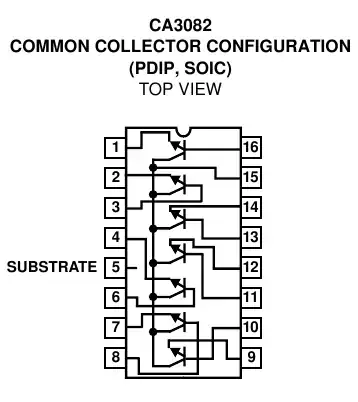
If you need more inputs/outputs you can use a common collector array chip such as CA3082. It will save you lots of space. Unfortunately I don't know a chip with common drain array built in.

Common Collector Array Chip

RMAAlmeida
  • 1,997
  • 15
  • 24
  • 3
    My favorite structure :), need to remember that it will not work with input down to gnd level (below 0.7V) and have gain slightly less than one. Also for higher input impedance you can replace npn win n-mos. – mazurnification Nov 22 '10 at 12:37
  • 1
    The problem with this configuration is that the BJT draws current (probably greater than the 500nA on the MCU inputs); also, the output will have an offset, reducing the dynamic range... – Thomas O Nov 22 '10 at 13:06
  • @Thomas O so you need a buffer that will load less then connecting direct to the MCU would? – Kellenjb Nov 22 '10 at 15:01
  • @kellenjb, Ideally, yes. – Thomas O Nov 22 '10 at 15:02
9

I find it hard to believe that wiring up little SC70 (or smaller) op amps is going to take up too much space on your board. Digikey has 5 pages of SC70 sized buffer amps that would probably do a good sight better job performance-wise than a common-collector BJT, and you could sprinkle them around the board as needed, meaning they'd take up no more space than that BJT.

akohlsmith
  • 11,162
  • 1
  • 35
  • 62
  • I need 6x SC70 packages then. Space is very constrained, I struggled to fit in the voltage divider resistors. Plus don't forget the traces, as I'm dealing with 2-layer. – Thomas O Nov 22 '10 at 13:04
  • 2
    @Thomas: What voltage divider resistors? For a buffer, you just short the inverting input to the output. – endolith Nov 22 '10 at 15:55
  • 1
    Think about a pair of quad op-amps. Each package needs one power and one ground connection. And the standard layout puts the output pin next to the (-) input. A gain-of-1 buffer would only save one pin per channel. – markrages Nov 22 '10 at 16:14
  • @markrages: 1 pin per channel might not sound like much but for my project it is a lot! – Thomas O Nov 22 '10 at 17:23
  • Quad op-amp requires 3.5 pins per channel. An emitter follower requires 5 pins per channel (three pins of transistor, two "pins" for resistor.) The CA3082 isn't available in really small packages last I looked. (BTW, a bunch of SC70 packages might be a pain to hand-solder). – markrages Nov 22 '10 at 17:29
  • 1
    6x SC70 for the buffers/opamps vs ... 6x SC70 for the transistors and 6x for the emitter resistors? I'm not sure why you think that using parts like this will be larger than the discrete solution. – akohlsmith Nov 22 '10 at 18:07
  • 1
    @Thomas: I wouldn't focus too much on the presumed big opamps. A quad opamp in TSSOP-14 package takes 32mm2 (5x6.4). I doubt you can do better with discrete components. – stevenvh Dec 05 '10 at 10:17
5

It seems after some discussion that you are looking for a buffer amplifier.

Digikey has a section for this. if you go to the main area for linear amplifiers and then select for buffer type and in stock you get quite a list. I selected for those with an input current of 2nA typical I got a relatively short list(like 10). This however does not give me an easy way to share the links, so you will have to click it yourself.

These are designed to give you the features you want and in a small package, now they normally come in groups of 2^n, so you will have to get a package of 8, but I am sure you can make it work.

Markrages had a bit of extra input to add in a comment:

Cautions about those buffer amps: Most of them are made for video signals and so they are high bandwidth / high current designs. That's a consideration if the circuit is battery powered. Also note that (the ones I looked at) are specialized, single vendor parts. More expensive and more availability risk than op-amps or transistors with standardized footprints. Engineers have a duty to only use oddball parts when their special features are necessary and relevant to the design.

Kortuk
  • 13,362
  • 8
  • 60
  • 85
  • 1
    @markrages, I specifically got this part due to conversation on the question about what Thomas needs. He specifically wants a buffer chip to save the traces to use an op-amp. I agree with your feedback. I will add it as a section in the answer if that is okay with you. – Kortuk Nov 22 '10 at 19:31
  • 2
    go for it. The question specifically excludes op-amps, for specious reasons, but they are exactly the solution to the problem here. In my opinion. – markrages Nov 22 '10 at 19:43
  • @markrages, he agreed that he wanted a buffer amplifier in the comments, which he specified he did not want the overhead of mapping the proper pins together. – Kortuk Nov 22 '10 at 20:16
  • 2
    yes, I saw that. note "the proper pins" are two adjacent pins on the opamp package, so it's not like there are extra traces running across the board to connect them. – markrages Nov 22 '10 at 20:21
  • @markrages, You are not alone on this, but I thought, why not, I will link a buffer amp. I still think for what is being done a 4 layer board will really help signal quality, EMC problems, and routing. – Kortuk Nov 22 '10 at 20:23
  • @Markrages - the cost is also in the extra pins, which take up space. I'm looking for a minimal pin count solution – Thomas O Nov 22 '10 at 20:23
  • @kortuk It's a low speed board. – Thomas O Nov 22 '10 at 20:23
  • @Thomas O, What is your fastest slew rate? – Kortuk Nov 22 '10 at 20:26
  • @Thomas its' your design, do what you want. Intersil have some buffers, EL5227 and friends. These parts need 4.5V supply. – markrages Nov 22 '10 at 20:30
  • @markrages, I have a 5V supply so that should be okay, but that is only in the pro version. – Thomas O Nov 22 '10 at 20:45
  • 5
    @Thomas O We have students who like to think there boards are low speed and don't need to worry about signal quality, EMC problems, and routing. It is amazing how many of those same students run into weird issues that are extremely hard to debug and happen on random occurrences. As @kortuk was asking, your slew rate has a HUGE effect on the bandwidth of your board. – Kellenjb Nov 22 '10 at 21:49
  • -1 since the suggestion to use video buffer amps is atrocious. You *do not* want to use those beasts without a solid 4 layer layout. The "buffer amplifier" the asker is looking for is an op-amp. These things are so tiny that you can sneeze and loose them. – Kuba hasn't forgotten Monica Feb 17 '15 at 20:31
1

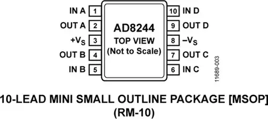
You are looking for AD8244 that has 4 channels in a MSOP-10 package (4 inputs, 4 outputs and 2 for gnd and power supply). There are others like that but are more difficult to find. The good thing is power supply can go from 3-36Vdc, the bad thing is the only 3MHz bandwith that is good enough for standard microcontrollers ADC but not enough for other uses. You could use only one opamp but use an analog switch/multiplexer to switch from different sources like the ADG1606 that can switch from 16 inputs AD8244 analog buffer