0

Raspberry Pi - Device circuit

I need to make a connection between the "Device"'s 2 wires using a Raspberry Pi, but I am unsure how to go about doing this (and I don't want to just play about with it and get it wrong as I might end up hurting my Pi).

The 2 wires coming from my Pi are a GPIO pin and ground, I figure if I make a direct connection between the "Device" and Raspberry Pi and set the GPIO pin low this would create a connection between the two wires, is this correct? Will I damage the Pi because of the 5v coming from the "Device"? If I set the GPIO pin high, will this break the connection?

Also the 0v/ground of both the Device and the Raspberry Pi are not common, does this affect things?

EDIT: Possible Circuit

Would something like this work

Thanks

AndrejaKo
  • 23,261
  • 25
  • 110
  • 186
OdinX
  • 821
  • 2
  • 9
  • 16
  • To answer this we need to know what you actually want to achieve by making this connection. Do you want to send some data to the device from the Pi? Do you want to send data from the device to Pi? Do you want to power the Pi from the device or device from Pi? What is the device actually? – AndrejaKo May 27 '13 at 14:01
  • I Just want to allow current to flow between the 2 wires on the Device, but allowing the Pi to control this. Hopefully that makes sense. Thanks – OdinX May 27 '13 at 14:03
  • It does make a little bit of sense and can be answered then. Traditional way is to have a switching element which will be controlled by the Pi. Do you know how much current you need to have going between the pins and how often do you need do make/break the connection? We'll need that to be able to recommend appropriate switching element and control mechanism on the Pi for it. – AndrejaKo May 27 '13 at 14:07
  • I will need to make/break the connection possibly hundreds of times a second. I don;t know quite how much current will be flowing, but in normal use, I just touch the wires together. While I was searching around I came across this [for the arduino](http://forum.arduino.cc/index.php?PHPSESSID=kuqfo7epguf9njig5beodhre37&topic=13894.msg103014#msg103014), would the same apply? – OdinX May 27 '13 at 14:10
  • Well sort of, but in my opinion, you **SHOULD NOT** use the Pi itself as a switch under any circumstances. Instead, since you need hundreds of switches a second, you should get a transistor to do the switching. For example, get an N-channel 3.3 V logic level MOSFET (can't tell you exact part number without current!) and connect its drain pin to device's +5 V, the source pin to device's 0 V pin. Next connect Pi's ground to device's 0 V pin and one of the Pi's GPIOs to the MOSFET's gate pin. If the current is low, you caould use a BJT plus resistor on base too instead of a MOSFET. – AndrejaKo May 27 '13 at 14:34
  • Ok, thanks. I don't have any MOSFETs kicking about so could I use an NPN transistor in the layout in the edit I made? – OdinX May 27 '13 at 14:49
  • NO. That edit will fry something. You would be shorting 5v to Ground! – Passerby May 27 '13 at 15:21
  • What device are you looking to use? You don't provide near enough information for us to be useful. – Passerby May 27 '13 at 15:23
  • Which is what I want to do? – OdinX May 27 '13 at 15:23
  • Its a floppy drives stepper motor. To step it once you have to short 2 pins, why does it matter what the device is? – OdinX May 27 '13 at 15:28
  • 1
    @Chief17 because you made it seem like you were shorting 5v to ground. That's a significant difference. And most stepper motors found in floppy drives tend to have multiple pins that need to be driven, with high current motor drivers (specialized /darlington transistors). See http://elabz.com/driving-a-bipolar-stepper-motor-with-arduino-and-uln2803ag/ for an arduino version of a similar project. – Passerby May 27 '13 at 15:32
  • All I need to do is short those 2 connections together using the Raspberry Pi, once for each step of the motor, the on-board circuitry of the floppy drive handles the rest. My wording may be off, but as far as I can tell I do want to short the 5v to ground – OdinX May 27 '13 at 15:45
  • @Chief17 I've read all the comments and it seems that you are not grasping what is being asked. The two pins you want to short together may carry substantial current and require a substantial driver circuit to acieve this. Saying you want to "short the 5V to ground" might as well be saying "short the power supply out". What are the names of the pins you want to short out and do you have a link, on the web to some technical documentation about the device? – Andy aka May 27 '13 at 15:59
  • @Chief17 if you are confident in that shorting those two would be what you need, then yes, the setup you have above would work, if you add a base resistor from the RPI gpio to the transistor base, and the transistor you use is strong enough for the current your motor needs. A 2n3906 is a PNP which only handles 200mA Max. A stepper motor can require current in the range of Amps. – Passerby May 27 '13 at 16:01
  • I may well not be grasping what is being asked as I am pretty new to electronics, but I __think__ I know enough to understand what is being asked. @Passerby Thanks, I think that's what I needed to know. The Raspberry Pi and the FDD are powered by separate wall adapters, will this cause an issue tying the two grounds together? Thanks – OdinX May 27 '13 at 16:06

2 Answers2

1

I did some experiments with couple of floppy drives I have and it appears that on the step pin, current is limited to around 5 mA. This means that we can indeed omit the collector resistor in this case. For base, I'd recommend a 1 kiloohm resistor. This will give us 3.3 mA coming into the base of the transistor, which should be more than enough to saturate usual small signal transistors.

Another point worth mentioning here is that same setup will most likely be needed for the direction pin as well, in order to prevent read heads from colliding with end-stops. Some floppy drives have security mechanisms which will prevent the stepper motor from forcing the head when the disk is inserted.

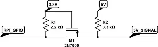
So the schematic looks something like this:

schematic

simulate this circuit – Schematic created using CircuitLab

OLD ANSWER:

I was about to make a really long comment, but then decided that it's better to turn it into an answer in hope that you'll be able to better understand our standpoint.

First, you're being difficult to work with! That may not be obvious to you, so I'll try to explain: You came to us with a question that looks basic and emits air of someone who isn't very experienced with electronics. In your question, you already have some idea for a solution to your problem (which is good, since in general we like it when people post questions they thought about) and then you exclusively ask for help related to implementation of your solution and are avoiding any information that could lead us to provide any other way to accomplish your real objective (which is bad).

The problem is that your solution (as you posted it) is in direct conflict with what we got as a part of basic electronics training! This is NOT a minor thing. I'll provide an analogy which will hopefully make this a bit easier to understand. Imagine this scenario: You just spend a whole evening drinking alcoholic beverages with your friends and can barely walk in a straight line. Now you're planing to get in your car and drive back home. While there is a chance that you will be able to get home safely, and it's true that many have done so in similar circumstances, there is also a great big chance that you will crash and kill yourself (or worse) and possibly someone else as well, making such a plan a bad idea in general.

It's relatively same with what you're providing. Sure, it seems that nothing bad is happening when you short the two wires together by hand (just as many drunk people drove safely to their homes), but it doesn't mean that it's the proper way to do it (unless we're really convinced that it's safe, for which we need details which you refuse to provide believing that your plan is correct).

Instead, the proper way to do this (assuming that you just have a simple control line that's being monitored by stepper motor driver) would be to place an appropriate resistor between the transistor and +5 V line, which will limit the current, so that we don't have a short-circuit there which could potentially destroy the driver.

Unfortunately, we can't tell you what type of resistor to use, since we don't know anything about your circuit and you refuse to provide information. Also the transistor itself needs to be appropriately dimensioned to be able to survive the current, provide low enough impedance to the current's path and switch quickly enough. Again we can't do that without any additional information.

Next, in comments I recommended a MOSFET since they can survive greater currents and dissipate less power that NPN transistors. You said that you don't have a MOSFET and want to use an NPN transistor. It's quite likely (based on my assumptions at least) that your NPN transistor would work just fine instead of a MOSFET, but for it and the Pi to work fine, you should use a resistor to control the current going from the Pi into the base of the transistor. Remember, Pi can provide only a little bit of current on its GPIO pins. Without knowing which transistor you have, we can't give you a good recommendation for the base resistor value. We can provide some values that may or may not work fine, but that's against what we're supposed to do and it's called bad engineering. You could also make this work without a base resistor on the transistor, but for how long it's going to work (if at all) and will the Raspberry Pi survive that, we can't tell. You'd be risking a $35 computer for a $0.1 resistor, which is pointless.

Finally, there's the coupling of two grounds. Since they're both grounds of two different wall adapters, I personally can't see anything bad happening if you short them together, as shown in your circuit. Some noise may couple into the Pi from the motor, but I don't think it will be a problem.

I hope that this provides a bit of background on the long comment chain.

AndrejaKo
  • 23,261
  • 25
  • 110
  • 186
  • Thanks for your answer. I resent that you feel I am being "difficult" to work with and that I am "refusing" to provide you with information. That is not the case, I have provided you will all of the information that I have to hand. Just a general FYI, every question I have posted on this part of stack exchange just reinforces the point being made [here](http://meta.electronics.stackexchange.com/questions/2777/does-ee-se-have-a-problem-with-the-treatment-of-newbies). I do appreciate the time you put into your answer and hopefully it will allow me to achieve what I set out to do, thanks. – OdinX May 28 '13 at 10:27
  • @Chief17 I do hope you achieve success! After reading the comment chain several times, I did notice that you eventually mentioned that you're directly driving a floppy drive, which I initially missed. Instead, I just understood that you're trying to drive some kind of stepper motor, so some blame can fall on me in this case. – AndrejaKo May 28 '13 at 10:33
  • In any case the question would have been easier to answer if you initially mentioned the floppy drive directly in the question text. I assume that you're trying to bring the step pin low. Knowing that, I believe that it's possible to provide an accurate answer to the question. Unfortunately, I don't have enough time to do that right now, but I'll be sure to post something useful once I get home later on today. – AndrejaKo May 28 '13 at 10:35
  • Yes, I think that's what I need to do. Thanks again for the answer. – OdinX May 28 '13 at 11:32
1

If the GPIO needs to be bidirectional, you are probably better off with a MOSFET and some pull-ups to the 3.3V and 5.0V sides. Like this:

schematic

simulate this circuit – Schematic created using CircuitLab

When both sides keep the signal high, both sides see high signals.

When RPI pulls the signal low, the voltage differential between source and gate means that the MOSFET conducts, and the 5V side sees a low signal as well (pulled to ground.)

When the 5V side pulls the signal low, the diode action of the MOSFET will pull the signal low on the other side.

In this way, the signal is bidirectional -- very useful for "general buffers" for GPIO, where the direction cannot be known a priori. Also useful for I2C busses. If you want to run multi-megahertz-rate signals (SPI, etc) then you may need smaller pull-up resistors, and live with a higher current consumption.

Jon Watte
  • 5,650
  • 26
  • 36